EZ4AXIS Page 2
Starting Up Using
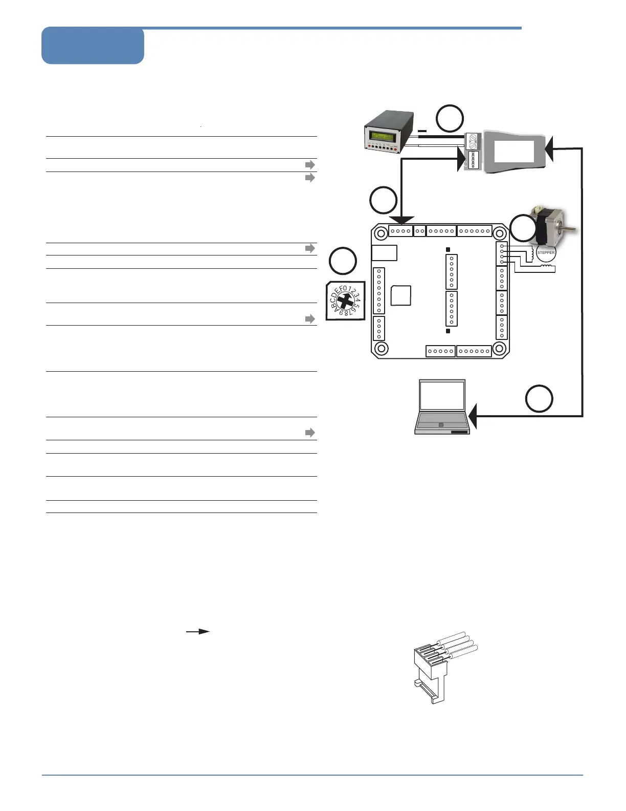
EZ Bus Connections
All Motion
www.allmotion.com
30097 Ahern Avenue, Union City, CA 94587 Telephone 408.460.1345 Email Info@allmotion.com
042814
Start with power supply OFF.
1. Download and install the EZCommander™ application from
www.allmotion.com/support./EZStepper Windows Application. (Use your own
terminal program for Mac or Linux. Some instructions may not apply.)
2. If using USB-to-RS485 Converter as shown, download and install appropriate
USB driver from www.allmotion.com/support.
3. Ensure power is OFF. Connect power supply to RS485 Converter.
4. Connect EZ Stepper to RS485 converter.
If using EZ Start kit, use cable provided. If not using kit, wire mating 4-pin
connectors pin-to-pin per the markings on the connector, for example pin A to
pin A. (See Wiring Note also.)
Turn power ON. Confirm that green Life LED slowly blinks. If not, look for bad
power connection.
5. Set address switch firmly to number 1 with Philips screwdriver.
6. Cycle power OFF/ON if address switch was moved in preceding step.
7. With USB cable from Converter to PC unplugged: Start the EZCommander
application (see other side of sheet for instructions if needed). Click “Settings,”
then “Rescan Ports.” Note available ports, then click “OK.”
8. Connect RS485 Converter to a PC USB port with the cable (supplied with
converter).
9. In EZCommander, click “Settings,” then “Re-Scan Ports.” Select the new port
that becomes available, and click “OK.” (For RS232 converter, the new port will
be com1.) If no new port appears, a problem with the USB driver is indicated.
Re-install the driver for your system.
10. In EZCommander, click “Send String
0
” to issue the command “/1&.” Confirm
return message showing product name and firmware version. If return
message says “No EZStepper Detected,” troubleshoot communications (page
3) before connecting motor.
11. With power OFF, connect stepper motor to Axis 1 as shown in the diagram.
(See Wiring Note also.)
12. Turn power ON.
13. In EZCommander, issue the command “/1A1
000
A
0R
.” Confirm that the motor
rotates back and forth.
14. With power OFF, connect stepper motors to the remaining three motor
connectors as shown for Axis 1 in the diagram.
15. Turn power ON.
16. Issue the command “/1A1
000
,1
000
,1
000
,1
000
A
0
,
0
,
0
,
0
R.” Confirm that all four
motors move simultaneously.
You're on your way! For other commands and hookups, see the full user
guide and wiring diagram on our website.
/
NOTE: If using RS232-to-RS485
Converter, disregard instructions for USB.
Troubleshooting:
See next page.
A B
RS485
Converter
USB-to-RS485
Converter shown.
A B
4
5
3
+
8
Computer Port
USB or DB9 cable
supplied with
Converter
EZ Bus
If using unipolar
6-wire motor, leave
center taps
unconnected. Do
not connect center
taps to each other.
EZ4AXIS
ADDRESS
STATUS LED
LIFE LED
SWITCH
STEPPER
CAUTION!
Do not connect or disconnect
motor with power applied.
Unplugging of or intermittant connection to an
inductive load
causes a high-voltage spark,
which will damage the driver.
Wiring Note
Always wire to the mating connectors supplied
on circuit board. Use crimp tool if you have it,
or else solder. (DO NOT solder to circuit board;
damage is likely. Also, DO NOT press in with a
screwdriver, because this makes unreliable
connections.)
1 2 3 4
11
+9 to 30V
Power Supply
Address
Switch
AXIS 1
MOTOR
AXIS 2
MOTOR
AXIS 3
MOTOR
AXIS 4
MOTOR
 Loading...