All Motion
www.allmotion.com
30097 Ahern Avenue, Union City, CA 94587 Telephone 408.460.1345 Email Info@allmotion.com
042814
Make sure address switch is detented exactly on position number 1.
(After resetting, power must be cycled to establish new address.)
Re-check that correct com port is selected.
Confirm good ground between PC and negative terminal of power
supply. First, measure resistance with power off; then check for voltage
drop with power on. Repair poor ground connections.
Issue command “/1&” and verify that a response identifying the product and
firmware version is received. If ok, motor connection may be miswired or
loose. If not ok, re-install USB driver. Continue to next item if not resolved.
Check continuity of communication data to EZStepper board at point 1
in diagram below. If not present, check at other points indicated.
Suspect failed component or faulty wiring/connector between point
where signal is absent and last point where signal is present.
If motor does not
respond to commands:
If motor misses steps at high speed:
Increase either the Move current or the supply voltage.
To increase Move current, issue an "m" for Fast Move Current and/or "l"
command (lower case L) for Slow Move Current. Example: /1m75 = set
current to 75% max.
Step misses typically happen in the middle of a move, where the motor
"catches" in the beginning and end, but stalls in the middle.
If motor direction is not consistent:
Check that coils of motor are securely connected at both ends.
This is typically caused when one of the coils has a loose connection.
2
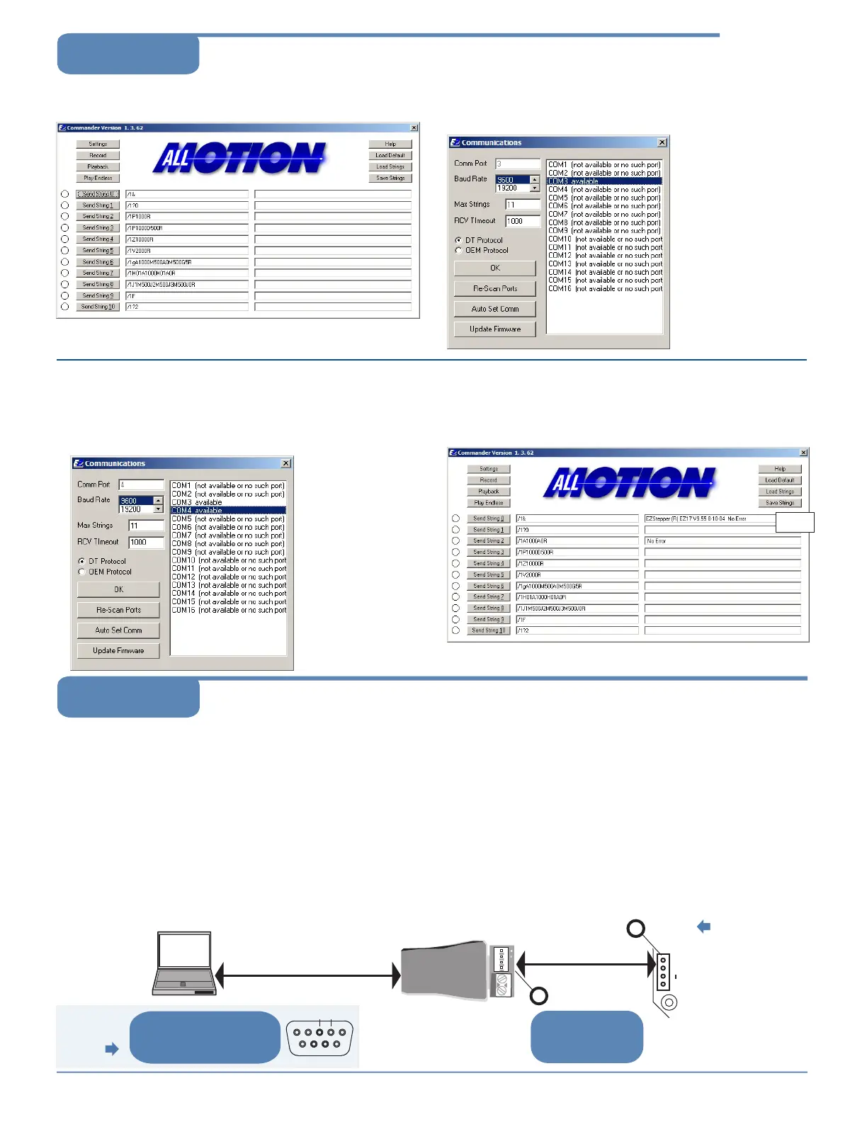
Click the Settings button to open the Communications window.
• Click Re-Scan Ports; note available ports; then click OK to close.
1
Open EZCommander.
3
Plug USB cable into the PC.
• Click Settings button, then Re-scan Ports. A new comm port
will become available (will be com1 if using RS232 Converter).
• Select the newly available comm port and click OK to close the
Communications Window.
Command strings
↑
Return messages
↑
4
Issue commands :
• Enter string in a left-hand field.
• Press adjacent Send String button to issue command.
• See return message in field to right.
Example
message
NOTE: USB cable
is disconnected for
this step.
Troubleshooting
Start with communications
cable unplugged.
NOTE: If using RS232 Converter, disregard instructions
for USB.
EZ4AXIS Page 3
Using EZCommander
TM
EZ Stepper
+ B A
EZ Bus cable
Pins A & B
1
2
Pins A & B
At both sets of A & B pins,
confirm 3V P-P pulses
centered on +2.5V. See
points 1 and 2.
Signal presence at point 1 suggests
problem in motor, EZStepper board, or
wiring to motor.
USB-to-RS485 Converter
shown.
23
If using
RS232-to-485
Converter
At DB9 connectors pins 3 and 2,
see 12V P-P pulses 100 µsec wide
(@9600 baud). Check at cable end
and at Converter connector.
A B
NOTE: If PC is
connected to USB
interface on
EZStepper board,
only check A & B pins
at point 1 as
described below.
 Loading...