This document is a user manual for the ALL-POWER Wood Chipper, covering models APWC420, APWC420E, APWC460E, and APWC9420C. It provides safety and operation instructions, maintenance guidelines, and troubleshooting information.
Function Description:
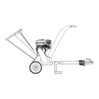
The ALL-POWER Wood Chipper is a powerful machine designed solely for chipping wood. It processes branches and woody materials into smaller chips, which can be used for various purposes such as mulch or compost. The machine features an infeed hopper where wood is fed, a chipping mechanism with reversible blades, and a discharge chute for expelling the processed material. Some models offer an electric start option, requiring battery connection.
Important Technical Specifications:
| Specification |
APWC420(E)/APWC9420C |
APWC460E |
| Engine |
15HP/420cc four strokes |
17HP/459cc four strokes |
| Power |
Gasoline/petrol |
Gasoline/petrol |
| Chipper Capacity |
4CBM/hour to 6CBM/hour |
4.5CBM/hour to 6CBM/hour |
| Wood Size |
6" |
6.2" |
| Permitted wood width |
12" |
12" |
| Chipper Blade |
twin reversible blades |
twin reversible blades |
| Tire |
16*6.5-8 |
16*6.5-8 |
| Overall Height |
58" |
58" |
| Overall Length |
73" |
73" |
| Width |
32" |
32" |
| Weight |
415LBS |
440LBS |
| Roller Max RPM |
2200RPM |
2200RPM |
Usage Features:
- Safety First: The manual emphasizes reading all safety rules and instructions before operation. It highlights the importance of wearing protective gear, including safety goggles, hearing protection, tight-fitting gloves, and steel-toed shoes.
- Operator Zone: Users are instructed to always stand in the designated "OPERATOR ZONE" during operation and never place any part of their body into an unsafe position.
- Wood Chipping Guidelines: The maximum diameter for woods and branches is 120mm. Users are warned against placing hands into the chute when loading and reaching or stepping across the rail while the chipper is running.
- Starting Procedure:
- Position the chipper on flat, dry ground and engage the front wheel brake.
- Ensure all nuts are tightened, and remove any stickers or cable ties from the stop button.
- Verify the fuel shut-off valve is in the "ON" position.
- Move the choke control lever to "CHOKE" (for cold engines).
- Move the throttle control lever to "FAST".
- For recoil start models, turn the ignition switch to "On", grasp the recoil starter handle, and pull rapidly to start.
- For electric start models, turn and hold the key in the start position until the engine starts.
- Slowly move the choke control lever to "RUN" once the engine is running well.
- Warm up a cold engine at half throttle for 3-4 minutes before advancing to maximum speed.
- Stopping Procedure:
- Move the throttle lever to "IDLE".
- For recoil start models, turn the ignition switch to "OFF".
- For electric start models, turn the key to "OFF".
- Troubleshooting: A dedicated section provides a troubleshooting table for common issues like the engine not starting, lacking power, smoking, or the machine not having full chipping power. Solutions include checking ignition, fuel, spark plug, air filter, oil level, and belt tightness.
- Assembly: The manual includes detailed instructions for assembling the wheels, infeed hopper, foot frame, tow bar, discharge chute, and connecting the emergency stop wire. For electric start models, battery assembly and wiring are also covered.
Maintenance Features:
- Regular Maintenance Checklist: The manual provides a checklist for routine maintenance, including:
- Before Each Use: Check engine oil level, general equipment condition, and belts.
- Every 3 Hours: Check tire pressure.
- Every 25 Hours: Clean engine exterior and cooling.
- Every 100 Hours: Replace air filter and spark plug.
- First time 5 hours: Change engine oil.
- Belt Adjustment and Replacement: Instructions are provided for adjusting belt tightness and replacing old belts. This involves unscrewing the belt cover, loosening specific bolts (engine fitting bolts, position bolts/M10 nuts), adjusting the position of the position bolts, and then tightening all bolts.
- Blade Replacement: Steps are outlined for replacing or using another edge of the blade. This involves removing the bearing cover and infeed hopper, using a "Special Spanner" to rotate the drum, and unscrewing/tightening the "Blade bolts" with a "T-Socket" tool.
- Blade Adjustment: The gap between the "Blade" and "Anvil" should be no more than 0.9mm. Adjustment involves loosening "Anvil bolts," using "Adjust bolts" to position the "angle bar," and then tightening all bolts and nuts.
- Lubrication: All bearings are sealed units and are designed to have sufficient lubricant for the machine's normal lifespan.
- Engine Service: Users are directed to refer to the engine manufacturer's user manual for specific engine maintenance procedures.
- Safety during Maintenance: Before any maintenance or inspection, the engine must be stopped, allowed to cool for five minutes, and the spark plug wire disconnected to prevent accidental starting. For electric start models, battery terminals must also be disconnected.