33
EN
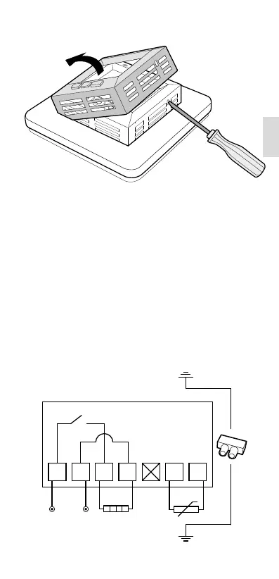
is connected with a connection clip in
the box. See wiring diagram below.
4. Insert the thermostat into the ap-
pliance box and screw tight with the
existing screws.
5. Fit the frame and front.
6. If the thermostat is mounted in a
multi-compartment frame, the internal
corners of this frame must be removed.
LOAD
LOAD
N
L
SENSOR
SENSOR
DO NOT USE
230 V
33
EN