EasyManuals Logo

Allen-Bradley PowerFlex 20-750-S1 User Manual

Allen-Bradley PowerFlex 20-750-S1
302 pages
To Next Page IconTo Next Page
To Previous Page IconTo Previous Page
Page #126 background imageLoading...
Page #126 background image
126 Rockwell Automation Publication 750-IN001O-EN-P - October 2014
Chapter 3 Lift and Mount the Drive
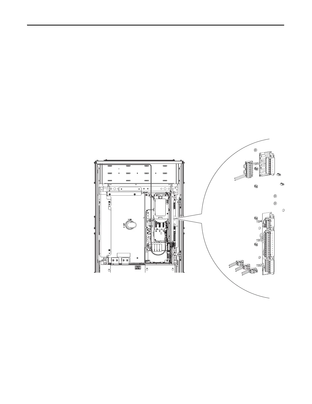
Common DC Input Drives
1. Disconnect the cabinet fan /cabinet blower assembly harnesses from
TB2-5 and TB2-6.
2. Disconnect the 120/240V control power input harness from TB2-3
and TB2-4.
3. Disconnect 120V UPS control power input (if used) from TB2-1 and
TB2-2.
4. Disconnect the digital I/O wiring (if used) from TB3
5. Disconnect the door interlock wiring (if used) from TB4
6. Disconnect the 120V UPS control power output wiring (if used) from
TB5.

Table of Contents

Questions and Answers:

Question and Answer IconNeed help?

Do you have a question about the Allen-Bradley PowerFlex 20-750-S1 and is the answer not in the manual?

Allen-Bradley PowerFlex 20-750-S1 Specifications

General IconGeneral
BrandAllen-Bradley
ModelPowerFlex 20-750-S1
CategoryController
LanguageEnglish

Related product manuals