EasyManua.ls Logo

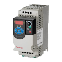
Allen-Bradley PowerFlex 4 - User Manual

Allen-Bradley PowerFlex 4
108 pages
Print Icon
To Next Page IconTo Next Page
Loading...
Adjustable
Frequency AC
Drive
FRN 7.xx
User Manual
www.abpowerflex.com

Table of Contents

Other manuals for Allen-Bradley PowerFlex 4

Questions and Answers

  • S
    Stephanie GlennJul 27, 2025
    What to do if Allen-Bradley PowerFlex 4 drive does not start from Start or Run Inputs wired to the terminal block?
    • C
      Connie HensonJul 27, 2025
      If the drive fails to start from the Start or Run Inputs, the issue could stem from several causes. First, clear any existing faults by pressing Stop, cycling power, or setting A100 [Fault Clear] to option 1, which is “Clear Faults”. Also, cycle the digital input if A051 - A052 [Digital Inx Select] is set to option 7 “Clear Fault.” Next, verify parameter settings, as incorrect programming of P036 [Start Source] or A051 - A052 [Digital Inx Select] could be the cause. Check the input wiring, ensuring it matches the wiring examples. Finally, confirm that the Sink/Source DIP switch setting is correct for your wiring scheme.
  • W
    williamslindaJul 31, 2025
    What to do if Allen-Bradley Controller drive is faulted?
    • L
      Linda SimpsonJul 31, 2025
      To address a faulted drive, try the following steps: Clear the fault by pressing the Stop button, cycling the power, setting A100 [Fault Clear] to option 1 which means “Clear Faults”, or cycling the digital input if A051 - A052 [Digital Inx Select] is set to option 7 which means “Clear Fault.”
  • G
    Gwendolyn WrightAug 4, 2025
    What to do if Allen-Bradley PowerFlex 4 Controller drive does not start from integral keypad?
    • V
      Virginia BrewerAug 4, 2025
      If the drive isn't starting from the integral keypad, first ensure the keypad is enabled by setting parameter P036 [Start Source] to option 0, which is “Keypad”. Alternatively, set parameter A051 - A052 [Digital Inx Select] to option 5, “Local,” and then activate the input. Also, check if I/O Terminal 01 “Stop” input is not present. If it is not, wire inputs correctly and/or install jumper.
  • J
    John HoffmanAug 8, 2025
    What to do if Allen-Bradley Controller motor does not start?
    • B
      Brandi MooreAug 9, 2025
      If the motor doesn't start, several factors could be at play. First, examine the power circuit, supply voltage, fuses, and disconnects. Ensure the motor is properly connected and that a start signal is present. For 2-Wire control, only the Run Forward or Run Reverse signal should be active. Check if I/O Terminal 01 is active and that P036 [Start Source] matches your setup. Also, verify that A095 [Reverse Disable] isn't preventing movement. Alternatively, the boost setting might be improper; in this case, set A084 [Boost Select] to option 2, which is “35.0, VT”.
  • N
    Natalie HortonAug 13, 2025
    Why Allen-Bradley PowerFlex 4 motor and/or drive will not accelerate to commanded speed?
    • P
      Pamela SimmonsAug 13, 2025
      If the motor and/or drive won't accelerate to the commanded speed, consider these potential causes: an excessive acceleration time, which can be resolved by reprogramming P039 [Accel Time 1] or A067 [Accel Time 2]. Also, an excess load or short acceleration times could force the drive into current limit; compare d003 [Output Current] with A089 [Current Limit] and either reduce the load or reprogram the acceleration times. Additionally, verify that d002 [Commanded Freq] and d012 [Control Source] are correct. Finally, check P035 [Maximum Freq] to ensure the speed isn't being limited by programming.
  • C
    Christopher ShahAug 17, 2025
    How to fix unstable motor operation in Allen-Bradley Controller?
    • A
      Alan CharlesAug 17, 2025
      To stabilize motor operation, ensure that the motor nameplate data is correctly entered into parameters P031, P032, and P033. Enable A097 [Compensation]. If instability persists, reduce the boost level using A084 [Boost Select].
  • D
    David DavisAug 22, 2025
    Why Allen-Bradley Controller drive will not reverse motor direction?
    • L
      lisa02Aug 22, 2025
      If the drive won't reverse the motor direction, consider these potential causes: * Check [Digital Inx Sel] and program the correct input for reversing mode. * Ensure the digital input is correctly wired. * Verify that the motor wiring is properly phased for reverse by switching two motor leads. * Check A095 [Reverse Disable] to ensure reverse is enabled.

Summary

Preface

Overview

General introduction to the manual's purpose and scope, including intended audience and required qualifications.

Who Should Use this Manual

Identifies the intended audience and required qualifications for using the drive.

Reference Materials

Lists recommended supporting documents for drive information, best practices, and safety guidelines.

Manual Conventions

Explains formatting, symbols, terminology, and abbreviations used throughout the manual.

Drive Frame Sizes

Describes how drive sizes are categorized for easier ordering, identification, and spare parts.

General Precautions

Crucial safety warnings and precautions for handling, installation, and maintenance of the drive.

Catalog Number Explanation

Details how to interpret the drive's catalog number to understand specific features and ratings.

Chapter 1 Installation and Wiring

Opening the Cover

Step-by-step instructions for safely accessing the drive's internal components for installation.

Mounting Considerations

Guidelines for properly mounting the drive to ensure optimal performance, ventilation, and safety.

AC Supply Source Considerations

Information on connecting the drive to various AC power sources, including ungrounded systems and MOV disconnection.

Input Power Conditioning

Addresses potential issues with input power quality and lists recommended solutions for optimal performance.

Ground Fault Monitoring

Explains safety grounding requirements, RFI filter grounding, and motor ground connections.

Fuses and Circuit Breakers

Details recommended branch circuit protection devices and guidelines for safe installation.

Power Wiring

Covers acceptable motor cable types, wiring practices, and reflected wave protection for safe power connections.

I;O Wiring Recommendations

Provides guidance on connecting digital and analog I/O signals for control, including wiring examples.

Control Wiring Block Diagram

Illustrates the terminal block layout and connections for various control signals and inputs.

Start and Speed Reference Control

Explains how to configure the drive for different start and speed command sources and their priority.

EMC Instructions

Outlines CE conformity requirements, directives, and guidelines for electromagnetic compatibility.

Chapter 2 Start Up

Prepare For Drive Start-Up

Pre-power-on checklist and essential steps before applying power, including DIP switch settings.

Applying Power to the Drive

Procedures for applying AC power and control voltages, and familiarizing with the integral keypad.

Integral Keypad

Explains the functions of the drive's keypad, LEDs, and display for operation and parameter navigation.

Viewing and Editing Parameters

Guides users on navigating and modifying drive parameters using the keypad interface.

Chapter 3 Programming and Parameters

About Parameters

Introduces different types of parameters (ENUM, Numeric, Bit) and their notation and conventions.

Parameter Organization

Shows how parameters are grouped into Display, Basic, and Advanced sections for easier navigation.

Display Group Parameters

Details parameters related to drive status, frequency, current, voltage, and fault codes.

Basic Program Group Parameters

Covers essential parameters for motor configuration, start/stop sources, and speed reference.

Advanced Program Group Parameters

Explains advanced parameters for digital inputs, relay outputs, communication, and braking settings.

Chapter 4 Troubleshooting

Drive Status and Faults

Explains how to interpret drive status indicators and identifies the two main types of drive faults.

Fault Descriptions and Actions

Lists common drive faults, their causes, and recommended corrective actions for resolution.

Common Symptoms and Corrective Actions

Addresses typical drive operational issues like starting problems or unstable operation with troubleshooting steps.

Appendix A Supplemental Drive Information

Drive, Fuse & Circuit Breaker Ratings

Provides recommended ratings for fuses and circuit breakers based on drive specifications and installation codes.

Specifications

Lists detailed drive specifications, including input/output ratings, operating conditions, and approvals.

Product Environmental Information

Links to information on product environmental compliance and estimated power loss data.

Appendix B Accessories and Dimensions

Product Selection and Drive Ratings

Guides for selecting drives and understanding their ratings, including catalog numbers and frame sizes.

Drive Dimensions

Provides detailed dimensional drawings for panel mount and flange mount drives for installation planning.

Accessories and Related Information

Covers accessories like brake modules, line reactors, filters, and HIM kits with their specifications.

Appendix C RS485 (DSI) Protocol

Network Wiring

Explains how to wire drives on an RS485 network using shielded cables, including daisy-chaining.

Parameter Configuration

Lists parameters required to configure the drive for network operation, such as data rate and node address.

Supported Modbus Function Codes

Details the Modbus function codes supported for communication, including read and write operations.

Logic Command and Reference Data

Describes how to send logic commands and references to the drive over the network via specific registers.

Reading Drive Status and Errors

Explains how to retrieve drive status, logic data, and error codes using network communication.

Appendix D RJ45 DSI Splitter Cable

Connectivity Guidelines

Provides rules for connecting peripherals using the RJ45 DSI splitter cable to ensure proper operation.

DSI Cable Accessories

Lists accessories for RJ45 DSI connections, including splitters, adapters, and cables.

Connecting an RS-485 Network

Illustrates how to connect drives to an RS-485 network using splitter cables and terminating resistors.

Allen-Bradley PowerFlex 4 Specifications

General IconGeneral
SeriesPowerFlex 4
Horsepower0.2-3 HP
EnclosureIP20
Output Frequency0-400 Hz
Power Range0.2…2.2 kW (0.25…3 HP)
Communication OptionsRS-485
Storage Temperature-40…85 °C (-40…185 °F)
Relative Humidity5-95% non-condensing
Control MethodVolts per Hertz

Related product manuals