Installation/Wiring 1-13
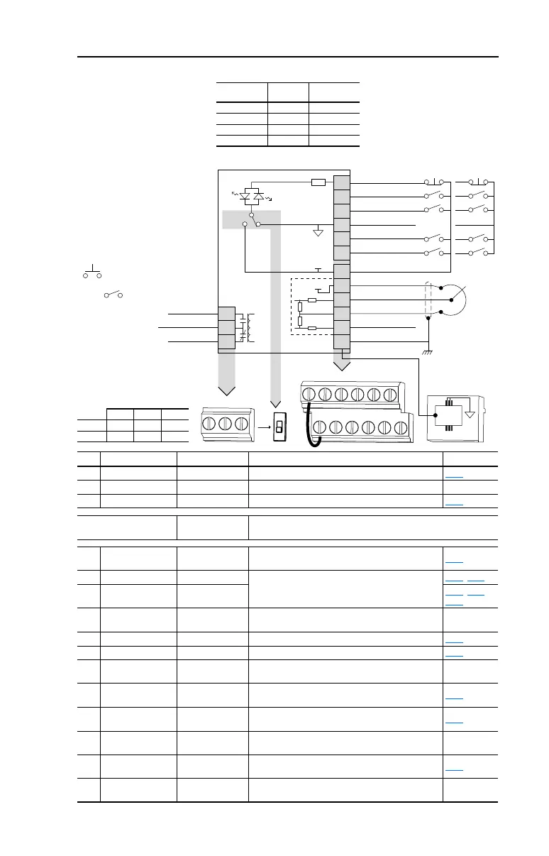
Figure 1.5 Control Wiring Block Diagram
No. Signal Default Description Param.
R1 Relay N.O. Fault Normally open contact for output relay. A055
R2 Relay Common – Common for output relay.
R3 Relay N.C. Fault Normally closed contact for output relay. A055
Sink/Source DIP Switch Source (SRC)
Inputs can be wired as Sink (SNK) or Source (SRC) via DIP Switch
setting.
01 Stop
(1)
Coast
The factory installed jumper or a normally closed input
must be present for the drive to start.
P036
(1)
02 Start/Run FWD Not Active
Command comes from the integral keypad by default. To
disable reverse operation, see A095 [Reverse Disable].
P036, P037
03 Direction/Run REV Not Active
P036
, P037,
A095
04 Digital Common –
For digital inputs. Electronically isolated with digital inputs
from analog I/O.
05 Digital Input 1 Preset Freq Program with A051 [Digital In1 Sel]. A051
06 Digital Input 2 Preset Freq Program with A052 [Digital In2 Sel]. A052
11 +24V DC –
Drive supplied power for digital inputs.
Maximum output current is 100mA.
12 +10V DC –
Drive supplied power for 0-10V external potentiometer.
Maximum output current is 15mA.
P038
13 0-10V In
(3)
Not Active
For external 0-10V input supply
(input impedance = 100k ohm) or potentiometer wiper.
P038
14 Analog Common –
For 0-10V In or 4-20mA In. Electronically isolated with
analog inputs from digital I/O.
15 4-20mA In
(3)
Not Active
For external 4-20mA input supply
(input impedance = 250 ohm).
P038
16 RS485 (DSI) Shield –
Terminal should be connected to safety ground - PE
when using the RS485 (DSI) communications port.
(3)
Only one analog frequency source may be connected at a time. If more than one reference is connected at the same
time, an undetermined frequency reference will result.
01
02
03
04
05
06
11
12
13
14
15
16
Stop
(1)
Start/Run FWD
(2)
Direction/Run REV
Digital Common
Digital Input 1
Digital Input 2
R1
R2
R3
Relay N.O.
Relay Common
Relay N.C.
+24V DC
+10V DC
0-10V In
Analog Common
4-20mA In
RS485 Shield
+24V
+10V
SRCSNK
Typical
SNK Wiring
Typical
SRC Wiring
18
RS485
(DSI)
R1 R2 R3
01 02 03 04 05 06
11 12 13 14 15 16
SNK
SRC
(1)
Potentiometer
must be
1-10k ohm
2 Watt Min.
30V DC 125V AC 240V AC
Resistive 3.0A 3.0A 3.0A
Inductive 0.5A 0.5A 0.5A
(1)
Important: I/O Terminal 01 is
always a coast to stop input except
when P036 [Start Source] is set to
“3-Wire” control. In three wire
control, I/O Terminal 01 is controlled
by P037 [Stop Mode]. All other stop
sources are controlled by P037
[Stop Mode].
Important: The drive is shipped with
a jumper installed between I/O
Terminals 01 and 11. Remove this
jumper when using I/O Terminal 01
as a stop or enable input.
(2)
Two wire control shown. For three
wire control use a momentary input
on I/O Terminal 02 to
command a start. Use a maintained
input for I/O Terminal 03 to
change direction.
P036
[Start Source]
Stop
I/O Terminal 01
Stop
Keypad Per P037 Coast
3-Wire Per P037 Per P037
2-Wire Per P037 Coast
RS485 Port Per P037 Coast

 Loading...


