1-2 Installation/Wiring
Mount the drive upright on a flat, vertical and level surface.
– Install on 35 mm DIN Rail.
or
– Install with screws.
Table 1.A Screw Mounting Recommendations
Protect the cooling fan by avoiding dust or metallic particles.
Do not expose to a corrosive atmosphere.
Protect from moisture and direct sunlight.
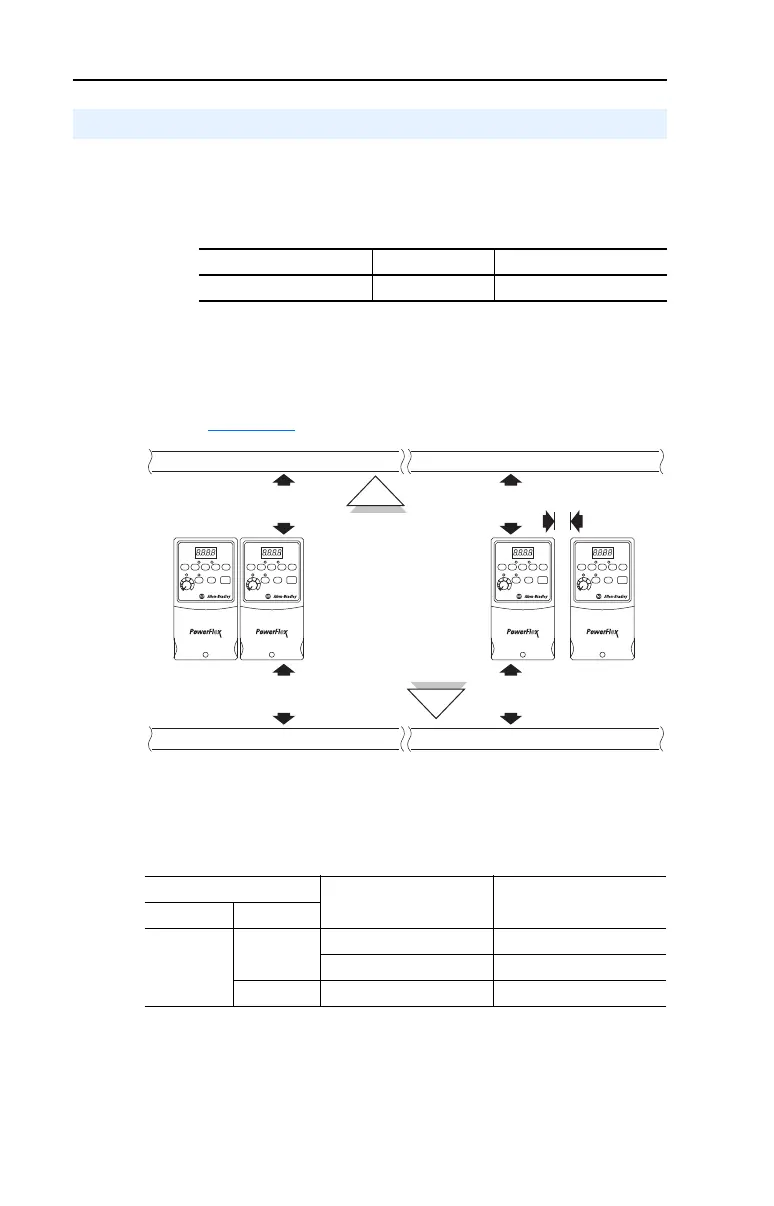
Minimum Mounting Clearances
Refer to Appendix B for mounting dimensions.
Ambient Operating Temperatures
Table 1.B Enclosure and Clearance Requirements
Debris Protection
A plastic top panel is included with the drive. Install the panel to prevent
debris from falling through the vents of the drive housing during
installation. Remove the panel for IP 20/Open Type applications.
Mounting Considerations
Minimum Panel Thickness Screw Size Mounting Torque
1.9 mm (0.0747 in.) M4 (#8-32) 1.56-1.96 N-m (14-17 lb.-in.)
Ambient Temperature Enclosure Rating Minimum Mounting
Clearances
Minimum Maximum
-10°C (14°F)
40°C (104°F)
IP 20/Open Type Use Mounting Option A
IP 30/NEMA 1/UL Type 1
(1)
(1)
Rating requires installation of the PowerFlex 4 IP 30/NEMA 1/UL Type 1 option kit.
Use Mounting Option B
50°C (122°F) IP 20/Open Type Use Mounting Option B
25 mm
(1.0 in.)
120 mm
(4.7 in.)
120 mm
(4.7 in.)
120 mm
(4.7 in.)
120 mm
(4.7 in.)
Mounting Option A
No clearance required between drives.
Mounting Option B
Closest object that
may restrict air flow
through the drive heat
sink and chassis

 Loading...


