Rockwell Automation Publication 750-IN001O-EN-P - October 2014 163
Power Wiring Chapter 4
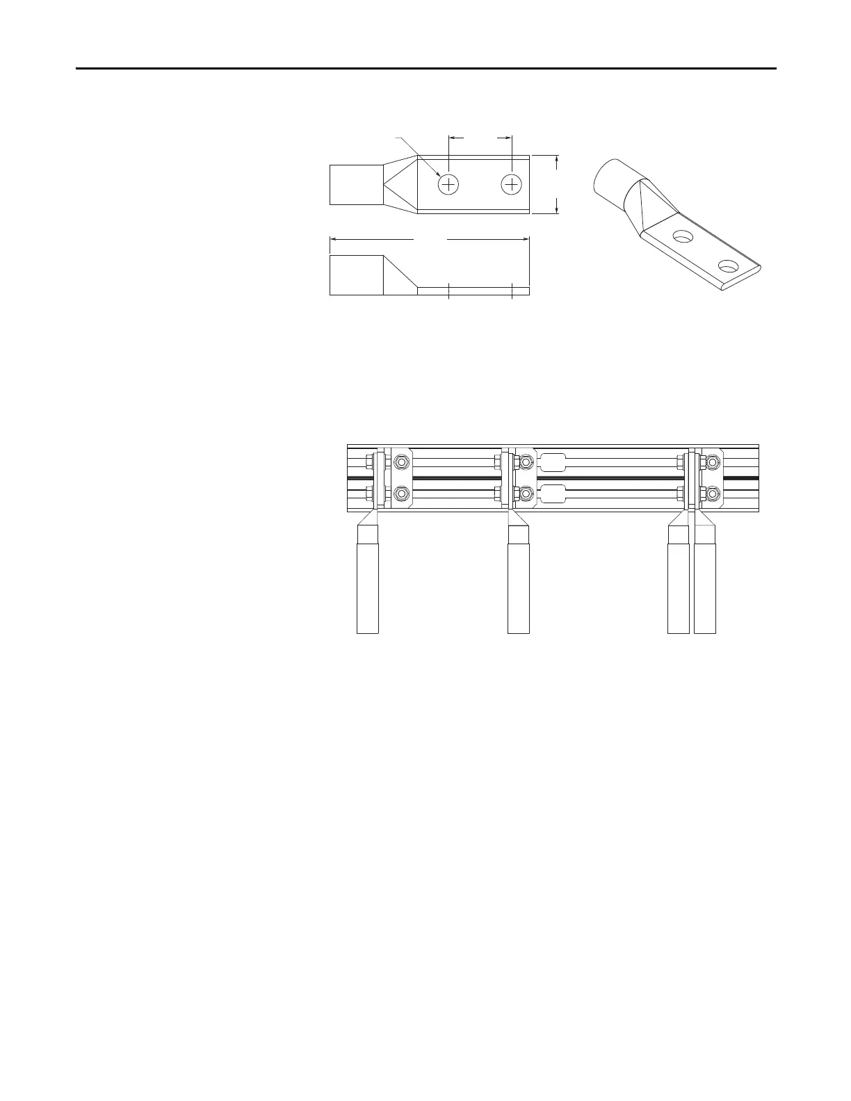
Figure 97 - Standard Barrel Lugs: Approximate Maximum Dimensions
Wires with appropriate terminals can be bolted to both sides of the L-brackets if
required. Frame 8 drives include two L-brackets per phase, allowing up to four
conductors per phase. Terminals should be attached to the L-brackets using M12
or 0.5 in. diameter bolts, nuts and washers. Bellville spring washers, or equivalent,
are recommended.
Figure 98 - Typical Lug Connection Options
44.5
(1.75)
31.8
(1.25)
127.0
(5.0)
ø 12.7
(0.5)
Left side of L-bracket. Right side of L-bracket. Both sides of L-bracket.
 Loading...


