Rockwell Automation Publication 750-IN001O-EN-P - October 2014 71
Lift and Mount the Drive Chapter 3
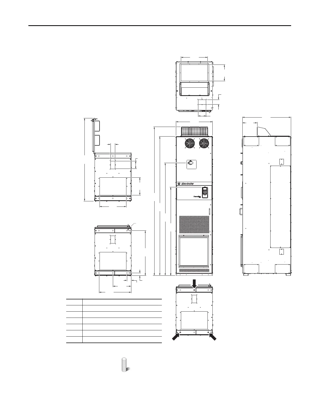
Figure 33 - IP20, NEMA/UL Type 1, MCC Style Cabinet, Floor Mount Frame 8
(Enclosure Codes L, P, W)
M12 (1/2 in.) Property Class 8.8 anchoring hardware recommended to
fasten the drive cabinet through its internal mounting angle to the
foundation. Anchor bolts may be pre-located and embedded in the
foundation prior to instillation.
2453
(96.6)
600
(23.6)
800
(31.5)
2300
(90.6)
1862
(73.3)
240
(9.4)
1374
(54.1)
292
(11.5)
127
(5.0)
76
(3.0)
300
(11.8)
531
(20.9)
ø18.0
(0.71)
742
(29.2)
43
(1.7)
69
(2.7)
➏
➎
➊
76
(3.0)
➊
➋
➍
1464
(57.6)
➌
127
(5.0)
440
(17.3)
440
(17.3)
270
(10.6)
➋
No. Description
➊ Power wiring conduit plates.
➋ Control wiring conduit plates.
➌ Optional exhaust hood.
➍ Disconnect switch (SW2). Common DC Input drives.
➎ Optional HIM.
➏ Recommended three-hole anchoring.
BOTTOM
BOTTOM
TOP
 Loading...


