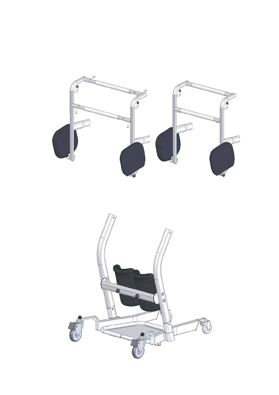
4. Insert the two tubular cross bars into the holes on the seat and handle bar
support units. Line up the small holes on the underside of the tubes with
the holes in the support units. Use the 4 set screws<A3> supplied to
tighten the assembly using the Allen key<T2>. The finished assembly is
shown below.
5. Insert the kneepad side support assembly into the base brackets as
shown above. The kneepads and arm curvature should be facing away
from the lockable casters.
 Loading...