Installation and User’s Guides
This document contains an abbreviated version of the installation instructions for the
MWS Series Access Points Installation Guide. For complete installation instructions and
installation safety statements, see the product documentation on the Allied Telesis web site
at www.alliedtelesis.com.
Safety and Electromagnetic Emissions Certificates
For Safety and Electromagnetic Emissions certificates, refer to MWS Series Access Point
Installation Guide.
European Union Restriction of the Use of Certain Hazardous
Substances (RoHS) in Electrical and Electronic Equipment
This Allied Telesis RoHS-compliant product conforms to the European Union Restriction of
the Use of Certain Hazardous Substances (RoHS) in Electrical and Electronic Equipment.
Allied Telesis ensures RoHS conformance by requiring supplier Declarations of Conformity,
monitoring incoming materials, and maintaining manufacturing process controls.
Europe - EU Declaration of Conformity
This device complies with Directive 2014/53/EU issued by the Commission of the European
Community. For more information, refer to MWS Series Access Point Installation Guide.
For the EU conformity statement, contact an Allied Telesis office listed on our web
site at http://www.alliedtelesis.com/contact.
Copyright 2017 Allied Telesis, Inc.
All rights reserved. No part of this publication may be reproduced without prior written
permission from Allied Telesis, Inc.
Redundancy Power Supply
The access point is equipped with two PoE+ capable LAN ports. In addition to the PoE+
ports, this device can drain power through the DC jack. When the power supply unit on
the access point fails, it switches to the PoE+ port to drain power.
The AC adapter is not included in the shipping box. You must purchase the
AT-MWS0091 AC adapter separately.
Kensington Key Hole
The access point has the Kensington key hole on the side panel.
Installation Orientations
The access point can be installed on a table, ceiling, or wall.
Installing the device with the Allied Telesis logo upside down is not allowed.
LEDs
The LEDs display status information.
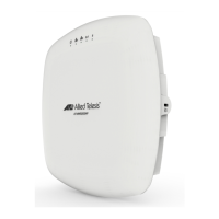
Quick Installation Guide
AT-MWS2533AP
Simultaneous Dual Band Access Point
Correct Table Installation Correct Ceiling Installation
Correct
Correct
Correct Incorrect
LED State Description
Power Green The access point is powered ON and operating
normally.
Blinking Green The access point is rebooting or software is
upgrading.
Off The access point is not receiving power.
Blinking Amber The configuration has being reset to the factory
default settings.
LAN 1 Green A valid link is established on the port at
1000Mbps.
Blinking Green Data is being transmitted/received at
1000Mbps.
Amber A valid link is established on the port at 10Mbps
or 100Mbps.
Blinking Amber Data is being transmitted/received at 10 Mbps
or 100Mbps.
Off No link is established.
LAN 2 Green A valid link is established on the port at
1000Mbps.
Blinking Green Data is being transmitted/received at
1000Mbps.
Amber A valid link is established on the port at 10Mbps
or 100Mbps.
Blinking Amber Data is being transmitted/received at 10 Mbps
or 100Mbps.
Off No link is established.
2.4GHz Wifi Green The 2.4GHz Wi-Fi interface is enabled.
Blinking Green Data is being transmitted/received at the
2.4GHz frequency band.
Off The 2.4GHz Wi-Fi interface is disabled.
5GHz Wifi Green The 5GHz Wi-Fi interface is enabled.
Blinking Green Data is being transmitted/received at the 5GHz
frequency band.
Off The 5GHz Wi-Fi interface is disabled.
1 2 3