506724-01Page 20 of 57 Issue 1108
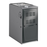
FIGURE 22
TYPICAL EXHAUST
PIPE CONNECTIONS IN UPFLOW DIRECT OR
NON−DIRECT VENT APPLICATIONS
TRANSITION
2”
2”
2”
3”
2”
2”
or
Pipe size determined in table 5
DO NOT transition
from smaller to larger
pipe in horizontal runs
of exhaust pipe.
EXHAUST
*2”
* When transitioning up in pipe size, use the shortest length of 2” PVC pipe possible.
NOTE − Exhaust pipe and intake pipe must be the same diameter.
or
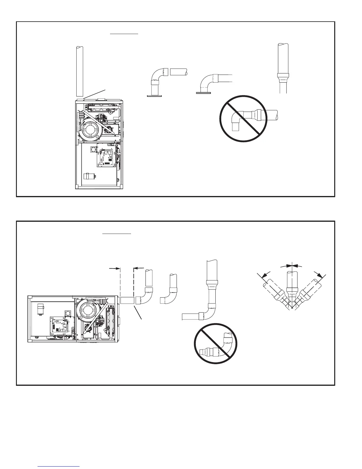
FIGURE 23
TRANSITION
SIDE VIEW
2”
2”
2”
2”
or
TYPICAL EXHAUST PIPE CONNECTIONS IN HORIZONTAL DIRECT OR
NON−DIRECT VENT APPLICATIONS
(RIGHT HAND DISCHARGE SHOWN)
3”
2”
45°
MAX
45°
MAX
DO NOT transition
from smaller to larger
pipe in horizontal runs
of exhaust pipe.
EXHAUST
12" max.
*2”
*2”
* When transitioning up in pipe size, use the shortest length of 2” PVC pipe possible.
NOTE − Exhaust pipe and intake pipe must be the same diameter.