506724-01Page 22 of 57 Issue 1108
1. Use transition solvent cement or a sheet metal screw
to secure the intake pipe to the inlet air connector.
2. Route piping to outside of structure. Continue with
installation following instructions given in general guide
lines for piping terminations and in intake and exhaust
piping terminations for direct vent sections. Refer to
Table 5 for pipe sizes.
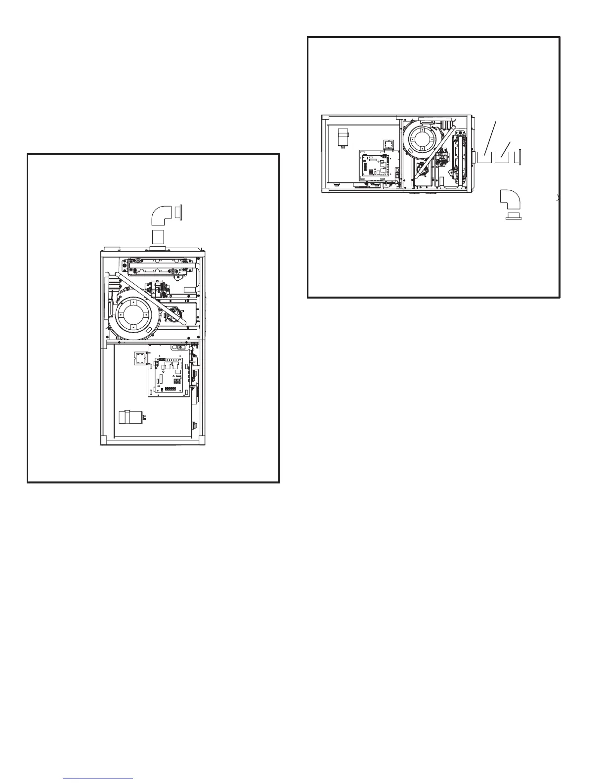
FIGURE 26
TYPICAL AIR INTAKE PIPE CONNECTIONS
UPFLOW NON−DIRECT
VENT APPLICATIONS
INTAKE
DEBRIS
SCREEN
(Provided)
NOTE − Debris screen and elbow may be rotated, so that
screen may be positioned to face forward or to either side.
FIGURE 27
TYPICAL AIR INTAKE PIPE CONNECTIONS
HORIZONTAL NON−DIRECT VENT APPLICATIONS
(Horizontal Right−Hand Air Discharge Application Shown)
INTAKE
DEBRIS
SCREEN
(Provided)
OR
NOTE − Debris screen may be positioned straight out
(preferred) or with an elbow rotated to face down.
coupling
PVC pipe