Paragraphs 230-234
ALLIS-CHALMERS
to remove transmission and mainshaft
as in paragraph
227.
Remove lock plate
(21) from rear of case and bump idler
gear shaft out toward the rear and
withdraw gear through the top of the
case.
Bushing in reverse gear is re-
newable and must be reamed after in-
stallation, to provide .001-.002 inch
clearance.
Model
WD
Prior 127008
First type transmissions have
a
straight
(not curved) gear shiiting lever and straight
cut gear teeth.
230.
BASIC PROCEDURE. Trans-
mission shafts, differential unit and
final drive bevel pinion and ring gear
are carried in the one housing. Over-
haul of any of the transmission shafts,
except the main drive shaft (transmis-
sion clutch shaft), requires removal of
transmission as outlined in paragraph
231.
231.
R&R
TRANSMISSION. Drain
oil from torque tube, transmission
and differential housing. Support trac-
tor under torque tube and rear por-
tion of main frame and transmission.
Remove rear wheels and final drive
assemblies as outlined in FINAL
DRIVE section, and differential and
bevel ring gear unit as outlined in
DIFFERENTIAL section. Remove
drawbar, battery, battery carrier and
power take-off shaft. Remove steering
column to transmission housing re-
taining cap screws. Disconnect brake
pedal rods and engage transmission
clutch. Remove rear platform and
power lift arms and shaft. Remove
main frame to transmission retaining
screws.
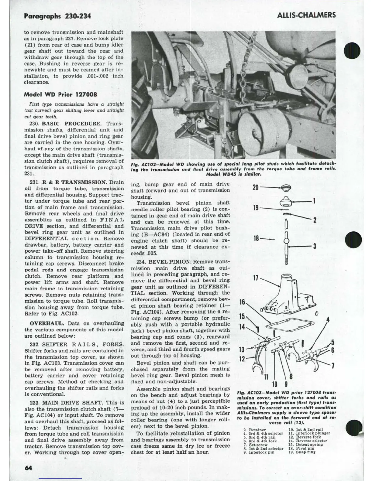
Remove nuts retaining trans-
mission to torque tube. Roll transmis-
sion housing away from torque tube.
Refer to Fig. AC102.
OVERHAUL. Data on overhauling
the various components of this model
are outlined below:
232.
SHIFTER RAILS, FORKS.
Shifter forks and rails are contained in
the transmission top cover, as shown
in Fig. AC103. Transmission cover can
be removed after removing battery,
battery carrier and cover retaining
cap screws. Method of checking and
overhauling the shifter rails and forks
is conventional.
233.
MAIN DRIVE SHAFT. This is
also the transmission clutch shaft (7—
Fig.
AC104) or input shaft. To remove
and overhaul this shaft, proceed as fol-
lows:
Detach transmission housing
from torque tube and roll transmission
and final drive assembly away from
tractor. Remove transmission top cov-
er. Working through top cover open-
16
Fig, AC 102—Model WD showing
use of
special long pilot studs which facilitate detach-
ing
the
transmission
and
final drive assembly from
the
torque tube
and
frame rails.
Model WD45
is
similar.
ing,
bump gear end of main drive
shaft forward and out of transmission
housing.
Transmission bevel pinion shaft
needle roller pilot bearing (2) is con-
tained in gear end of main drive shaft
and can be renewed at this time.
Transmission main drive pilot bush-
ing (B—AC84) (located in rear end of
engine clutch shaft) should be re-
newed at this time if clearance ex-
ceeds .005.
234.
BEVEL PINION. Remove trans-
mission main drive shaft as out-
lined in preceding paragraph, and re-
move the differential and bevel ring
gear unit as outlined in DIFFEREN-
TIAL section. Working through the
differential compartment, remove bev-
el pinion shaft bearing retainer (1—
Fig.
AC104). After removing the 6 re-
taining cap screws bump (or prefer-
ably push with a portable hydraulic
jack) bevel pinion shaft, together with
bearing cup and cones (3), rearward
and remove the first, second and re-
verse,
and third and fourth speed gears
out through top of housing.
Bevel pinion and shaft can be pur-
chased separately from the mating
bevel ring gear. Bevel pinion mesh is
fixed and non-adjustable.
Assemble pinion shaft and bearings
on the bench and adjust bearings by
means of nut (4) to a just perceptible
preload of 10-20 inch pounds. In mak-
ing up the assembly, install the wider
roller bearing (one with longer roll-
ers) next to the bevel pinion.
To facilitate reinstallation of pinion
and bearings assembly to transmission
case freeze same in dry ice or freeze
chest for at least half an hour.
11
10
9
Fig,
AC103-Model WD prior 127008 trans-
mission cover, shifter forks
and
rails
as
used on early production (first type) frons-
missions. To correct
an
over-shift condition
AlliS'Chalmers
supply
a
sleeve type spacer
to
be
installed
on the
forward
end of
re*
verse rail (13),
2.
Retainer
4.
Srd
&
4th selector
5.
3rd
&
4th rail
6. 3rd
&
4th fork
7.
Set screw
8. 1st
&
2nd selector
9. Interlock pin
10.
1st
&
2nd rail
11.
Interlock plunger
12.
Reverse fork
14.
Reverse selector
16.
Detent spring
18.
Pivot pin
19.
Snap ring
64