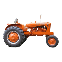
Do you have a question about the Allis-Chalmers WC and is the answer not in the manual?
Provides general specifications for the WD 45 Diesel tractor, including engine details, bore, stroke, and displacement.
Details ignition firing order, valve tappet gaps, valve face angles, and timing specifications for the WD 45 Diesel.
Lists critical dimensions, capacities, and clearances for engine components like crankshaft journals and pistons.
Provides general specifications for various non-diesel Allis-Chalmers tractor models.
Details tune-up specifications, including firing order, tappet gaps, and ignition timing for non-diesel models.
Lists critical dimensions, capacities, and clearances for various engine components across different models.
Explains how to adjust steering gear bearings and backlash for various front axle and tricycle configurations.
Details the Gemmer steering gear used on B-C models, including adjustment procedures for end play.
Procedure for adjusting worm shaft end play by managing shims and locknuts.
Guidance on adjusting sector shaft end play for proper steering gear operation.
Step-by-step instructions for removing and reinstalling the engine and clutch assembly.
Procedure for removing and reinstalling the cylinder head, including bolt tightening sequences.
Details on correctly timing valves by meshing crankshaft and camshaft gears.
Procedure for camshaft removal, installation, and bushing renewal for B, C, CA, and RC models.
Instructions for removing and installing connecting rod and piston assemblies for B, C, CA, and RC models.
Procedure for removing and installing connecting rod and piston assemblies for Model G.
Details on crankshaft support, bearing renewal, and end play adjustment for models other than Model G.
Procedure for flywheel removal and installation on specific models, including ring gear timing marks.
Details on carburetor models used and their specifications for non LP-Gas applications.
Information on the LP-gas system for WD45 tractors, including carburetor and economizer details.
Explains the operational principles of the Ensign Model W LPG regulator.
Procedure for adjusting engine speed by shortening or lengthening the quadrant lever rod.
Details on generator, regulator, and starter motor specifications and testing.
Instructions for setting ignition timing for various models using magneto or battery ignition.
Step-by-step instructions for removing and reinstalling the engine and clutch as a unit.
Procedure for removing and reinstalling the cylinder head, including cleaning and tightening instructions.
Details on mushroom type tappets, their clearance, and removal procedure.
Procedure for removing and installing timing gears, checking backlash, and adjusting camshaft end play.
Instructions for camshaft removal, installation, and bushing service.
Procedure for removing and installing piston and connecting rod units, including torque specifications.
Instructions for crankshaft removal, bearing renewal, and adjustment.
Methods for testing and identifying faulty injection nozzles.
Guidance on using a nozzle tester for checking spray pattern, leakage, and opening pressure.
Procedure for timing the injection pump to the engine, including checking and re-timing steps.
Information on the Model B-C hydraulic pump, including R&R and inspection procedures.
Procedure for testing and adjusting the hydraulic pump and its valves.
Instructions for adjusting brakes on later production tractors using screwdriver.
Procedure for removing the tractor platform and brake band assembly.
Details on belt pulley units supplied without a hydraulic lift system.
Procedure for adjusting bearings and backlash for belt pulley gears.
Specific data for PTO units on RC, WC, WD, WD45, and WF models.
Procedure for disassembling the mechanical power lift unit on RC and WC models.
| Manufacturer | Allis-Chalmers |
|---|---|
| Model | WC |
| Production Years | 1933-1948 |
| Fuel Type | Gasoline |
| Transmission | 4-speed |
| Type | Tractor |
| Engine Type | Allis-Chalmers 4-cylinder |


 Loading...