Copyright © 1996 General Motors Corp. 6–13
REBUILD OF SUBASSEMBLIES
(3) Restrain plug 27 and remove pin 22.
(4) Remove plug 27, capacity pin 26, spring
25, and regulator valve 24.
(5) Restrain plug 30 and remove snapring 32.
(6) Remove plug 30, spring 29, and autoflow
valve 28.
(7) Remove O-ring 31 from plug 30.
b. Assembly
NOTE:
Check the configuration and position of all compo-
nents (Foldout 13). Check the identification of all
springs (Paragraph 8–2). All valves, when dry, must
move freely by their own weight in their bore.
(1) Install a new O-ring 31 onto plug 30.
(2) Install autoflow valve 28, short-tipped
end first, into valve body 23. Into the same bore, install
spring 29 and plug 30 (with O-ring 31 in place).
(3) Depress plug 30 and install snapring 32.
(4) Install regulator valve 24, wider diameter
first, into valve body 23. Into the same bore, install
spring 25, capacity pin 26, and plug 27.
(5) Depress plug 27 and install pin 22.
(6) Install spring 21 into valve body 23. Into
the same bore, install priority valve 20, smaller diame-
ter first, and plug 19.
(7) Depress plug 19 and install pin 22.
6–8. TRANSFER PLATE ASSEMBLY
(Retarder Models) (Foldout 13)
a. Disassembly
(1) Remove snapring 9 from feedthrough
seal 10.
(2) Disconnect two connectors 8 from sole-
noids 7.
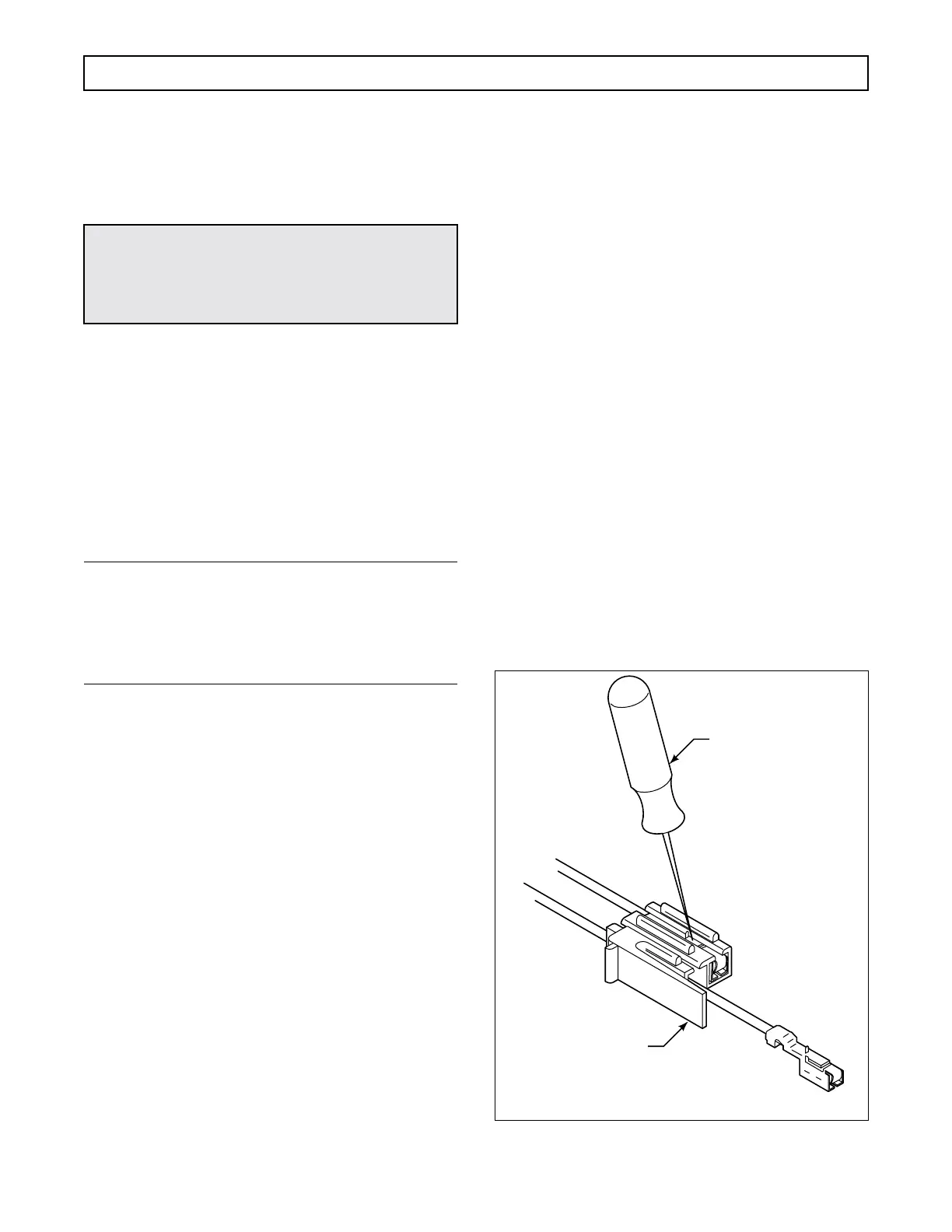
(3) Remove the terminals from connectors 8
as follows:
• Using remover tool J 38125-13, depress
locktab on terminal (accessible in slot of
connector) and push the terminal out front
of the connector (Figure 6–22).
• Cut the terminal between the core and the
insulation crimp (to minimize wire loss).
• Repeat the process for the remaining
terminals.
(4) Remove harness 11 from transfer plate 14.
(5) Remove a pipe plug 12 and a pin 13 for
each solenoid 7 and remove the two solenoids.
Figure 6–22. Terminal Removal
WARNING!
Autoflow valve plug 30 is spring-loaded and must
be restrained while snapring 32 is being re-
moved.
J 38125-13
V03118
SOLENOID CONNECTOR
 Loading...


