ITA ENG FRA ESP DEU POR
6-1622192 rev. 14 21/09/2012 2/9
SAFETY WARNINGS
•
Some points of the electrical card are under voltage. Therefore, the installation, the opening and the programming of board have to be done
only by qualified staff. All the operations executed by the user do not require box opening.
•
Providing the use of a device that ensures omni polar disconnection of power from the control unit. This device may be or an interrupter
(directly connected to the power terminals) with a minimum distance of 3 mm. between the contacts in each pole, or a device integrated into
the power network.
•
For connecting the card and the motors, we recommend to use cable with double isolation as provided through restrictions and in any case,
individual conductor must have a minimum cross section not less than 1mm² and not more than 2.5mm².
•
The manufacturer declines all responsibilities for no compliance with these warnings.
•
This central unit is furnished with a test circuit for the photocells. For wiring these photocells, see diagram on page 5.
•
It is recommended to check the absorptions of all devices connected to the output of control unit, such as warning lights, photocells, safety
devices and so, according to their limits established on the table of technical features.
•
The correct functioning of the product is not guarantee in case of non-observance of these limitations.
•
To maximise the transmitter reach, it is not necessary to pay attention to the placing of the receiving antenna: it must not be positioned near
walls and/or metallic shields. The terminals on shielded cable of the antenna have to be tightly closed.
•
The corded antenna is necessary for obtaining the highest equipment capacity, otherwise the reach would be reduced to a few meters.
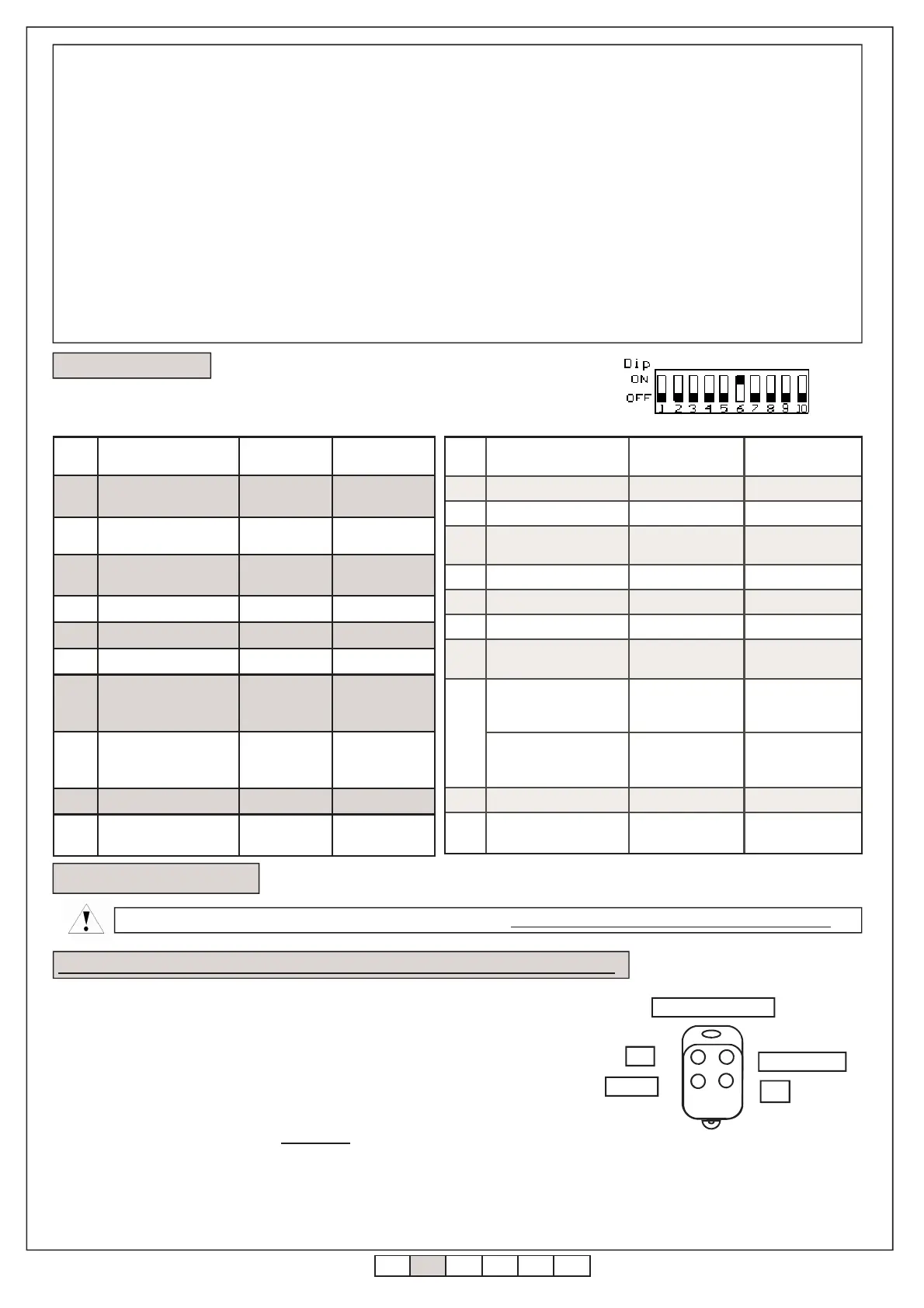
The control board is supplied with the dip.switch set as indicate on the figure beside.
In the table are resumed the functions selectable by these dip-switch.
4. Factory settings.
5. Self-lerning transmitter.
The self-learning procedure of every individual transmitter must always be carried out with the gate closed
,
Pressing and releasing the learning taste turn on the flashing light; so, transmit with the
transmitter to learn, considerino that:
•
The tastes must be learned one by one
•
With the first button learned “a”, the step-by-step order is given.
•
With the second button learned “b”, the “pedestrian” command is imparted.
•
With the third button learned “c”, the DOWN command is given.
•
With the fourth button learned “d”, the UP order is imparted.
It is advisable to learn the a, b, c, d keys sequentially.
When an UP or DOWN button is activated while imparting the instructions (the “c” or “d” button over the transmitter), the blinking light will flash
briefly for indicating that the key was seen from the system. It is very important to verify that each transmission of all the buttons is correctly
received by central unit.
NOTA: The successive learning can now be executed also with the memorized transmitter. The operative modalities are reported here
following:
N°
dip
Function Dip OFF Dip ON
1 Step-by-step
Open-stop
Close-stop
Open-Close
2 Water hammer Enabled Disabled
3 Photocells
movement
stops
arrest and rever-
sal of motion
4 Pre-blinking Active Active
5 Condominium function Not active Active
6 Safety control Enabled Disabled
7
Limit switch operating
mode
In Closing
End of opera-
tion
Start of slo-
wdown
In closing
8
Limit switch operating
mode
In Opening
End of opera-
tion
Start of slo-
wdown
In opening
9 *** *** ***
10
Immediate Automatic
re-closing
Disabled Enabled
N°
dip
Function Dip OFF Dip ON
1 Step-by-step Open-stop-Close Open-Close
2 Water hammer Enabled Disabled
3 Photocells
movement stops
arrest and reversal
of motion
4 Pre-binking Not active Active
5 Condominium function Not active Active
6 Safety control Enabled Disabled
7
Limit switch operating
mode
End of operation
Beginning of slo-
wdown
8
Slowdown functioning
mode
(only if dip 7 is ON)
Start of slowdown
on limit switch in
OPENING
Start of slowdown
on limit
switch in CLOSING
Slowdown functioning
mode
( only if dip 7 is OFF)
End of operation
Limit switch not
connected
9 Open gate Symmetrical Asymmetrical
10
Immediate Automatic re
-closing
Disabled Enabled
a
c
b
d
PP
DOWN
PEDESTRIAN
UP
TRANSMITTER
5.1 Memorization of the transmitters / of the transmitter of preparation 4 channels
 Loading...