EasyManua.ls Logo

Alpha Antenna MagLoop - User Manual

Alpha Antenna MagLoop
2 pages
Print Icon
To Next Page IconTo Next Page
Loading...
SPECIFICATIONS
10-40M OR 6M, 2M, & 440MHz – 100W SSB, 50W CW, OR 10W DIGITAL
40-80M – 20W SSB, 10W CW, OR 5W DIGITAL
10-40 Meters 40-80 Meters
ASSEMBLY & TUNING
A) Insert the Center Support Mast onto the tuning box.
B) Ensure the black Coax Mounting Clips are installed above the Rubber Grommet on the Center Support Mast.
C.1) 10-40 Meters; Screw the shorter outer loop’s PL-259 connectors onto the SO-239 connectors on either side
of the tuning box. Insert the outer loop into the slot of the black Coax Mounting Clip located at the top of the
center support mast.
C.2) 40-80 Meters; Connect the two longest elements (Default outer loop and Booster Cable) in series with the
Barrel Connector. Form a double loop and secure it with the black nylon coaxial clips. Screw the PL-259s on either
end of the double loop onto the two SO-239s on the tuning box. Then place one of the concentric outer loops
into the top slot of the black Coax Mounting Clip with two slots and the other double loop into the bottom slot.
NOTE - A minimum curvature with a 110-degree bend of the outer loop should be used for C.1 & C.2.
D) Insert the small Feed Loop into the slot of the bottom most black Coax Mounting Clip.
E) Attach your feedline to the SO-239 on the t-connector on the small Feed Loop.
HF TUNING: Turn your tuner off or set it into by-pass mode. Then start with MINIMUM power & select your
frequency, then turn the black knob on the grey Alpha Match till your rigs meter peaks in SSB mode with the
loudest audible noise floor. Second, watch your SWR meter dip as you transmit and ‘Fine Tune’ the loop.
NOTES: Turning the knob to the left lowers the frequency and to the right raises it. It takes about 3 full turns of
the tuning knob to fully cycle the variable air capacitor, at which point there is a 30% friction clutch that enables
the knob to keep turning without causing damage to the reduction gears. Also, not that the Coax Mounting Clip
with the small Feed Loop can be moved up or down the center support mast to lower SWRs.
Question and Answer IconNeed help?

Do you have a question about the Alpha Antenna MagLoop and is the answer not in the manual?

Overview

The Alpha Antenna MagLoop is a portable HF magnetic loop antenna designed for amateur radio enthusiasts, offering a versatile solution for various frequency bands and power levels. Its primary function is to provide efficient radio communication in a compact and portable form factor, suitable for both fixed and portable operations.

Function Description:

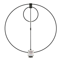
The MagLoop operates as a high-frequency (HF) magnetic loop antenna, which is known for its efficiency in radiating and receiving radio signals, especially in situations where space is limited or stealth operation is desired. It achieves this by using a large loop of conductor that acts as the primary radiating element, coupled with a smaller feed loop for impedance matching. The antenna's design allows for quick setup and tuning across a wide range of frequencies, making it ideal for field deployments, emergency communications, or casual use from a backyard or park. The system includes a tuning box with an Alpha Match control, which allows users to precisely tune the antenna to their desired frequency and achieve a low Standing Wave Ratio (SWR) for optimal performance. The modular design, with interchangeable outer loops, enables operation on different bands, from HF to UHF.

Important Technical Specifications:

The MagLoop offers a broad range of operational capabilities across multiple frequency bands and power levels:

  • 10-40M, 6M, 2M, & 440MHz:
    • SSB (Single Sideband): Up to 100 Watts
    • CW (Continuous Wave): Up to 50 Watts
    • Digital Modes: Up to 10 Watts
  • 40-80M:
    • SSB: Up to 20 Watts
    • CW: Up to 10 Watts
    • Digital Modes: Up to 5 Watts

These specifications highlight the antenna's versatility, allowing users to engage in various modes of communication, from voice (SSB) to Morse code (CW) and modern digital modes, while adhering to appropriate power limits for each band. The lower power limits for the 40-80M band suggest that this configuration might be more suitable for QRP (low power) operations or situations where a smaller footprint and lower power consumption are critical.

Usage Features:

Assembly:

The assembly process is straightforward and modular, designed for quick deployment:

  1. Center Support Mast: The first step involves inserting the Center Support Mast onto the tuning box, forming the central structure of the antenna.
  2. Coax Mounting Clips: Ensure the black Coax Mounting Clips are correctly positioned above the Rubber Grommet on the Center Support Mast. These clips are crucial for securing the radiating and feed loops.
  3. Outer Loop Configuration:
    • 10-40 Meters: For these bands, the shorter outer loop is used. Its PL-259 connectors screw onto the SO-239 connectors on either side of the tuning box. The loop is then inserted into the top slot of the black Coax Mounting Clip.
    • 40-80 Meters: This configuration requires the two longest elements (Default outer loop and Booster Cable) connected in series using a Barrel Connector to form a double loop. This double loop is secured with black nylon coaxial clips. The PL-259s on either end of the double loop connect to the two SO-239s on the tuning box. One concentric outer loop goes into the top slot of the black Coax Mounting Clip, and the other double loop goes into the bottom slot. A minimum curvature of 110 degrees is recommended for the outer loop in both C.1 and C.2 configurations.
  4. Small Feed Loop: The small Feed Loop is inserted into the slot of the bottom-most black Coax Mounting Clip.
  5. Feedline Connection: The user's feedline is attached to the SO-239 on the t-connector of the small Feed Loop.

HF Tuning:

Tuning the MagLoop for optimal performance involves a precise, two-step process:

  1. Initial Setup: Before tuning, ensure your tuner is off or in bypass mode. Select your desired frequency and start with minimum power.
  2. Alpha Match Adjustment: Turn the black knob on the grey Alpha Match control. In SSB mode, listen for your rig's meter to peak, indicating the loudest audible noise floor. This initial adjustment brings the antenna close to resonance.
  3. Fine Tuning: While transmitting, observe your SWR meter. Continue to "Fine Tune" the loop by adjusting the black knob until the SWR dips to its lowest point.

Tuning Notes:

  • Frequency Adjustment: Turning the knob to the left lowers the frequency, while turning it to the right raises it.
  • Variable Air Capacitor: The variable air capacitor requires approximately three full turns of the tuning knob to cycle completely through its range.
  • Friction Clutch: A 30% friction clutch is integrated into the design, allowing the knob to keep turning without damaging the reduction gears, which protects the internal mechanism from over-rotation.
  • SWR Adjustment: The Coax Mounting Clip holding the small Feed Loop can be moved up or down the center support mast to further lower SWRs, providing an additional degree of fine-tuning for impedance matching.

Optional 6, 2, 440MHz Add-On Element:

For multi-band VHF/UHF operation, an optional add-on element is available, with installation instructions provided via a YouTube link. The process involves:

  1. T-connector Removal: Remove the t-connector from the small inner feed loop.
  2. T-connector Re-connection: Re-connect the t-connector to the coax end that has a soldered pin in its PL259.
  3. Barrel Connector Attachment: Attach the barrel connector of the 6M, 2M, 440MHz add-on element to the PL259 without the soldered center pin.
  4. Loop Formation: Form a single loop using these coaxial elements.
  5. Element Securement: Secure the end of the add-on element to the coax of the inner loop using a nylon coax clip.
  6. Tuning: Tune this configuration by sliding the element in and out of the nylon coax clip.

Maintenance Features:

The manual implicitly suggests a level of durability and user-serviceability through its detailed assembly and tuning instructions. The friction clutch in the tuning mechanism is a key design feature that prevents damage to the reduction gears, extending the lifespan of the tuning system. The modular nature of the antenna, with separate components for the loops and tuning box, implies that individual parts could potentially be replaced if damaged, rather than requiring a full antenna replacement. Regular inspection of the coaxial connections, clips, and mast for wear and tear would be good practice to ensure continued optimal performance and longevity. The use of nylon coaxial clips for securing elements also indicates a design choice aimed at preventing metal-on-metal abrasion or shorting, contributing to the antenna's overall robustness.

Alpha Antenna MagLoop Specifications

General IconGeneral
BrandAlpha Antenna
ModelMagLoop
CategoryAntenna
LanguageEnglish

Related product manuals