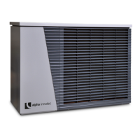
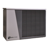
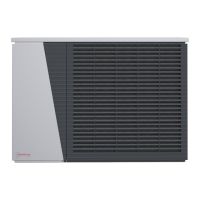
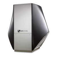
Do you have a question about the Alpha-InnoTec LWD 70A and is the answer not in the manual?
Explains symbols for operators, technicians, and hazard warnings.
Covers safety for qualified personnel, electrical connections, and general warnings.
Addresses refrigerant hazards, unit operation safety, and environmental concerns.
Advises regular checks of the condensate drain for blockages.
Lists included components and accessories.
Recommends using manufacturer-approved accessories.
Covers unit placement, spacing, transport, and general safety.
Provides sound pressure levels for different models and distances.
Explains sound level increases for multiple units and directivity factors.
Covers wall penetration, wall brackets, and floor bracket installation.
Specifies requirements for condensate pipe installation.
Covers flushing the heating circuit and connecting pipes.
Emphasizes correct pipe dimensions and sealing for connections.
Highlights electrical safety, compliance, compressor rotation, and power supply.
Covers pressure relief, overflow valves, buffer tanks, and circulating pumps.
Discusses domestic water heating and hot water tank sizing.
Explains VDI 2035 standards for preventing scale, corrosion, and pH control.
Specifies insulation for pipes and emphasizes water quality monitoring.
Outlines installation checks, electrical verification, and completion reporting.
Warns about electrical shock and refrigerant leaks during dismantling.
Covers refrigerant recovery, cylinder handling, and unit marking.
Lists heat pump types, performance data, and operational limits.
Covers sound levels, unit data, dimensions, connections, and electrical specs.
Lists unit components, safety features, and controller information.
Provides performance, application limits, and sound level data.
Lists unit data, electrical specs, and component details.
Shows heating capacity (Qh) and pressure loss (Δp) vs. flow.
Displays Coefficient of Performance (COP) and Power Consumption (Pe) vs. temperature.
Shows heating capacity (Qh) and pressure loss (Δp) vs. flow.
Displays Coefficient of Performance (COP) and Power Consumption (Pe) vs. temperature.
Shows heating capacity (Qh) and pressure loss (Δp) vs. flow.
Displays Coefficient of Performance (COP) and Power Consumption (Pe) vs. temperature.
Shows heating capacity (Qh) and pressure loss (Δp) vs. flow.
Displays Coefficient of Performance (COP) and Power Consumption (Pe) vs. temperature.
Shows cooling capacity (Q0) and power consumption (Pe) vs. temperature.
Displays Energy Efficiency Ratio (EER) vs. heat sink temperature.
Shows heating capacity (Qh) and pressure loss (Δp) vs. flow.
Displays Coefficient of Performance (COP) and Power Consumption (Pe) vs. temperature.
Shows cooling capacity (Q0) and power consumption (Pe) vs. temperature.
Displays Energy Efficiency Ratio (EER) vs. heat sink temperature.
Provides overall unit dimensions and connection port details.
Illustrates required safe distances and protection areas around the unit.
Shows drilling layout for wall bracket installation variant V1.
Details floor bracket installation and hydraulic connections for variant V2.
Shows foundation requirements and wall feedthrough for variant V3.
Details foundation plan and hydraulic connections for variant V4.
Provides drilling pattern for wall bracket, variant BB1.
Provides drilling pattern for wall bracket, variant BB2.
Shows foundation view, wall feedthrough, and fixing points for V3.
Shows foundation view, hydraulic connections, and conduit details for V4.
Illustrates required functional spacing around the unit.
Details connecting condensate pipes to ground or wastewater systems.
Explains internal condensate pipe connection with syphon.
Shows electrical diagram for power supply, compressor, and fan.
Details control board, sensors, and valve connections.
| Brand | Alpha-InnoTec |
|---|---|
| Model | LWD 70A |
| Category | Heat Pump |
| Language | English |

