30
Alpha CD12S/20S/28S - Component Replacement
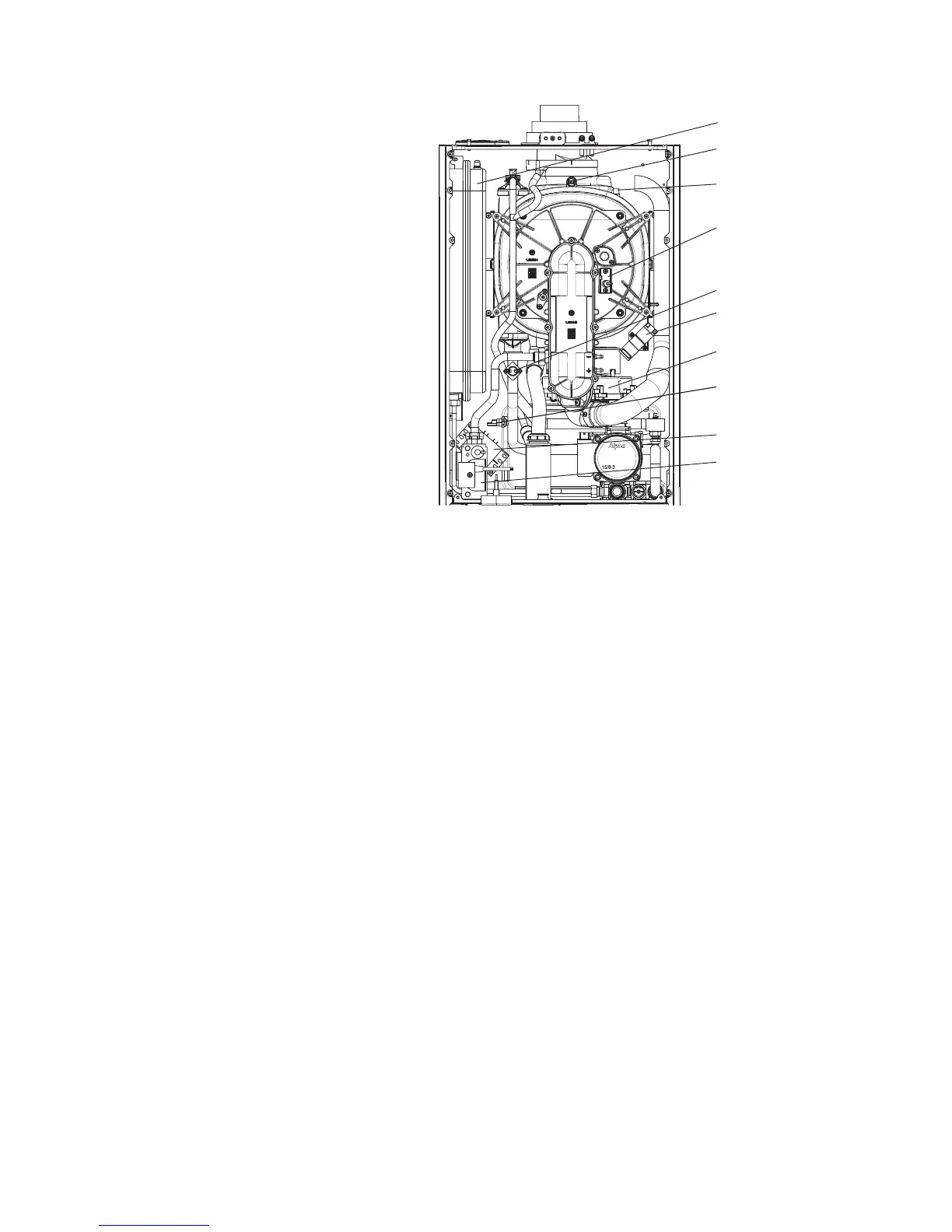
8.6 FAN - Fig. 31
1. Gain access behind the room sealed chamber
as described in Section 8.1.
2. Remove the screw securing the air inlet pipe and
remove the pipe.
3. Disconnect the fan wiring and remove the two
screws securing the fan. Withdraw the fan.
4. Re-assemble in reverse order using a new fan.
Ensure that the pressure tubes are connected
correctly.
5. Re-assemble and test the boiler as described in
Routine Servicing, Section 7.4 paragraphs 5 to 9.
8.7 IGNITION GENERATOR - Fig. 31
1. Gain access behind the front panel as described
in Section 8.1.
2. Disconnect all the wiring from the ignition generator.
3. Remove the screw securing the generator and
remove.
4. Secure the new generator in position and re-
connect the wiring.
5. Re-assemble in reverse order.
8.8 TRANSFORMER - Fig. 31
1. Gain access behind the front panel as described in Section 8.1.
2. Remove the two screws securing the transformer and remove the transformer.
3. Disconnect all of the wiring noting their position.
4. Fit the new transformer and re-assemble in reverse order.
8.9 OVERHEAT THERMOSTAT - Fig. 31
1. Gain access behind the front panel as described in Section 8.1.
2. Disconnect the wiring from the overheat thermostat.
3. Remove the two screws securing the overheat thermostat and remove it from the flow pipe.
4. Fit the new overheat thermostat and re-assemble in reverse order.
8.10 FLUE TEMPERATURE SENSOR - Fig. 31
1. Gain access behind the front panel as described in Section 8.1.
2. Disconnect the wiring.
3. Using a 13 mm spanner, turn the sensor 90° anti-clockwise and withdraw it from the heat exchanger.
4. Fit the new sensor and re-assemble in reverse order.
8.11 GAS VALVE - Fig. 31
Note: The replacement of the gas valve or PCB must be carried out by a Gas Safe registered engineer with the use of a flue
analyser.
1. Gain access behind the front casing as in Section 8.1.
2. Disconnect the positive pressure tube from the gas valve.
3. Loosen the one screw securing the electrical plug and disconnect the plug.
4. Disconnect the burner manifold pipe union and the gas inlet pipe union.
5. Remove the two manifold screws from beneath the boiler and lift out the valve assembly.
6. Lift out the gas valve.
7. Fit the new assembly and re-assemble in reverse order and test for gas tightness.
8. Light the boiler. (Refer to Commissioning, Section 5.4) and adjust the gas valve as described in the instructions supplied
with the replacement valve.
9. Complete re-assembly as described in Routine Servicing, Section 7.4 paragraphs 5 to 9.
Fig. 31
Flue temperature
sensor
Heat exchanger
thermal fuse
Ignition electrodes
Overheat thermostat
Ignition generator
Fan assembly
Primary temperature
sensor
Transformer
Gas valve
Expansion vessel