5
Alpha CD12S/20S/28S - Technical Data
2.8 FLUE LENGTHS
CD Easy-Flue 500 mm with terminal and 90° bend. A CD Easy-Flue 1000 mm with terminal and 90° bend is also available.
CD 750 mm and 1000 mm flue extensions are available.
Length of Flue Required:-
Rear Flue = wall thickness + 160 mm (includes terminal). This is without back frame, add 45 mm if the wall jig is used.
Side Flue = wall thickness + distance between wall and side of boiler + 245 mm (includes terminal)
Vertical Flue = distance from top of boiler side panel to required roof position minus 1000 mm for vertical terminal assembly
Maximum horizontal flue length = 12 m.
Maximum vertical flue length including terminal is 15 m.
Each additional CD 90° Bend is equivalent to 1.3 m of flue length.
Each CD 45° Bend is equivalent to 0.9 m of flue length.
The CD Vertical Flue terminal assembly is equivalent to 1 m of flue length.
2.9 AVAILABLE PUMP HEAD FOR CENTRAL HEATING
gal/min
3.7
2.8
2.3
1.8
0.7
Btu/h
86 700
64 000
53 000
42 200
18 100
kW
25.40
18.70
15.60
12.35
5.30
Output (50/30°C) Available pump head
metres
2.3
3.5
3.8
4.0
4.6
feet
7.6
11.6
12.6
13.2
15.2
litre/min
16.6
12.6
10.5
8.3
3.2
20°C 20°C
Flow rate
This information is based on 20°C system design temperature difference.
Note: For outputs upto 28 kW refer to Section 3.7.
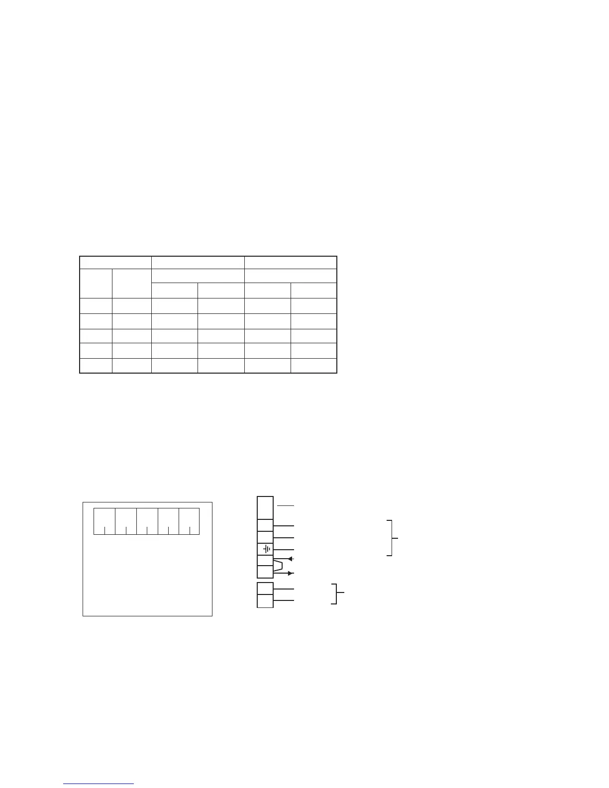
2.10 ELECTRICAL CONNECTIONS
Note: This Appliance Must Be Earthed
An optional integral two channel Clock kit is available if required.
Note: Only use an Alpha two channel clock. Do not fit any single channel clocks.
L
N
1
2
F2A
3
4
Fig. 1
Boiler terminal block
Clock connections
1. Ensure wires are connected
correctly
2. Only fit the Alpha recommended
2 channel clock. Other clocks
could cause damage.
WARNING
12345
Internal 2 Channel Clock Terminals
White
wire
Grey
wire
Black
wire
Blue
wire
Brown
wire
Fuse - Always t fast blow 2 A
230/240 V ~ 50 Hz
Fuse supply 3 A
Note: To connect external
control, remove link from
terminals 1 and 2 and
connect a 230/240 V
switched live to terminal 1
Live (Brown wire)
Neutral (Blue wire)
Earth (Green/Yellow wire)
Switched Live
230/240 V (Ch1 ON)
Ch1 OFF
Ch2 ON
Use only when internal
two channel clock is
tted