17
Fig. 21
Alpha CD13R, 18R, 24R - Installation
4.8 CONNECT THE MAINS SUPPLY - Fig. 20
1. Gain access to the boiler terminal block by removing one
screw at the top centre of the front panel, then lift up and
remove panel. Release the two fixing screws (one each
side) securing the control panel. Lower the control panel.
Refer to Technical Data, Section 2.9 for connection details.
2. Note: This boiler has been fitted with a mains supply cable.
However, if it is necessary to fit an alternative supply cable,
ensure the cable clamp that has been fitted is removed and
connect as follows:-
Remove the two screws securing the terminal block cover
from the back of the control box (see Fig. 20). Pass the
mains supply cable through the grommet and cable clamp
and connect as follows:- Brown to L, Blue to N and Green/
Yellow to
. Ensure correct polarity.
Note: Ensure that the length of the earth wire is such
that if the supply cable is pulled out of its clamp the live
and neutral wires become taut before the earth wire.
The main terminal block can be removed by pulling it off
the pins to give easy access to the terminals.
Do not switch on the electrical supply at this stage.
3. If an external control, i.e. room thermostat or external clock is to be fitted, remove the terminal block cover and remove the
link between terminals 1 and 2. Pass the cable through the cable clamp and connect it to terminals 1 and 2. Connect the
external pump cable to the boiler terminal block by passing the cable through the cable clamp and connecting it to L, N
and
terminals for the external pump. Replace the terminal block cover. (Refer to Section 2.9).
Note: Ensure the pump is always connected to the boiler terminal block.
4. Replace the terminal block, ensuring it is located correctly on the plastic pins and replace the cover.
5. Ensure that there is sufficient free cable to allow the control panel to be raised and lowered then tighten the cable clamp screws.
6. Leave the control panel open until commissioning procedures have been completed.
7. Carry out electrical system checks - Short circuit, Polarity, Earth continuity and Resistance to earth with a suitable multimeter.
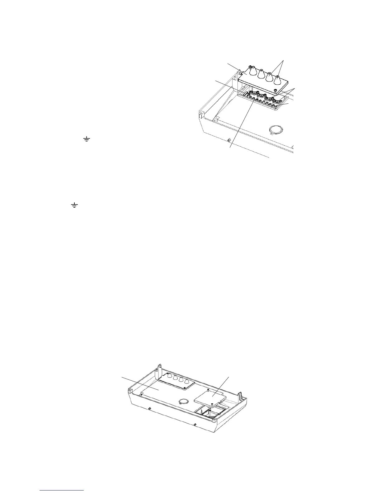
4.9 FIT THE CLOCK KIT - Fig. 21
Ensure the electrical supply to the boiler is isolated.
Note: Only use an Alpha two channel clock. Do not fit a single channel clock.
1. Remove the two screws securing the clock cover at the rear of the control panel.
2. Remove and discard the clock blanking panel.
3. Insert the clock into the opening and secure in place with the screws supplied - do not overtighten the screws..
4. Disconnect the clock wiring from the terminal block and connect it to the clock as follows:-
Brown wire to terminal 1, Blue wire to terminal 2, Black wire to terminal 3, Grey wire to terminal 4 and White wire to terminal
5, (or as per the instructions supplied with the clock). Ensure wiring is correct.
Note: Before the clock is fitted, remove the link between terminals 1 and 3 on the clock wiring harness fitted to the boiler.
5. Replace the clock cover. Do not overtighten the fixing screws.
6. Leave the control panel open until commissioning procedures have been completed.
Rear of control panel
Clock cover
Fig. 20
Terminal block cover
Fuse
Cable clamps
Remove link to
connect external
controls. See
Wiring diagram
Connect external
pump. See wiring
diagram.
Note: The pump
must always be
connected to this
terminal block.
Grommets