22
7.3 CLEANING THE BOILER
1. Remove any deposits from heat exchanger using a
suitable soft brush. Do not use a brush with metallic
bristles.
2. Check the condition of the combustion chamber
insulation panels. Any damaged panels must be
replaced. (Refer to Component Replacement,
Section 8.17).
3. Check the condition of the burner injector on the
combustion chamber front assembly, carefully clean
it with a soft brush if necessary.
Do not use a brush with metallic bristles as this might
damage the injector.
4. Remove any deposits from the heat exchanger coils.
This can be done by suction or water sprayed onto
the coils. Ensure all electrical components are
protected from water. Any water used to clean the
heat exchanger will drain to the condensate trap.
5. Unscrew and replace the injector if it appears
damaged.
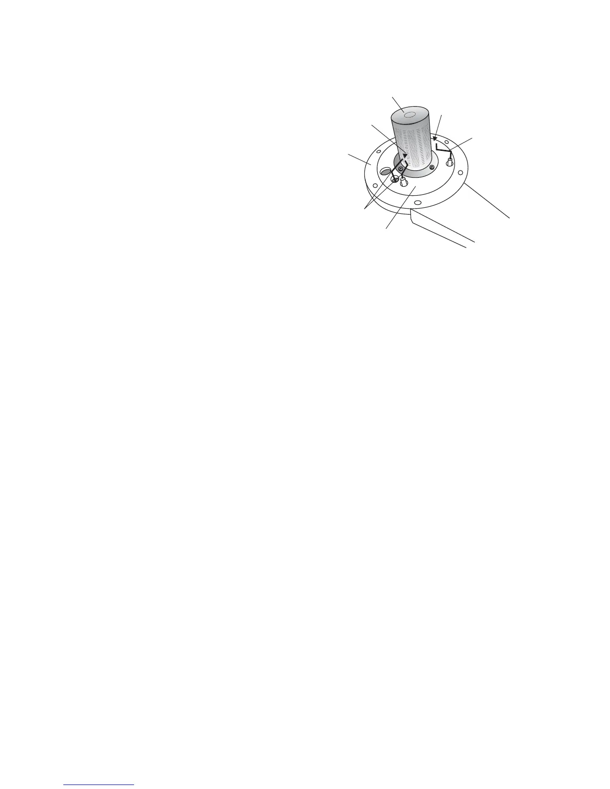
6. Remove the four screws securing the burner (see
Fig. 26) and remove the burner. Clean the burner with a soft brush and check that the flame ports are clear. Blockages
may be removed with a stiffer brush. Tap the burner, open end down, to remove any deposits from inside.
7. Check the condition of the electrodes.
9. Check the spark gap, positioning and height of the electrodes. See Fig. 26.
10. Unscrew the condensate trap drain cap, clean and remove any deposits from the trap.
Note: Before removing the cap, ensure that the water released from the trap can be contained to avoid spillage.
The trap will contain no more than 200 cc of condensate water. Replace the drain cap.
7.4 RE-ASSEMBLE THE BOILER
1. Replace the burner, ensuring it is located correctly and secure it in position using the four screws previously removed.
Important: Before replacing the combustion chamber front assembly, pour at least 200 cc of water into the coils of the
heat exchanger. This is to ensure the condensate trap is full of water before operating the boiler.
2. Replace the combustion chamber front assembly, ensuring it is correctly located.
3. Ensure the electrode lead is connected and the seal is in position in the bottom of the room sealed chamber.
4. Test the connections for gas soundness and re-commission, Sections 5.4 and 5.5.
5. Ensure that the room sealed chamber panel seal is intact and in position, replace the panel ensuring it has been located
correctly and secure it in position with the screws previously removed.
6. Raise the control panel and secure in position with the two screws provided.
7. Replace the front case panel and secure in position.
8. Check the operation of the boiler. (Refer to Boiler Operation, Section 6).
9. Return all controls to their original settings.
Alpha CD13R, 18R, 24R - Routine Servicing
Fig. 26
Flame sensing
electrode
Gap 11 mm
Ignition electrodes
Gap3-4mm
Burner
Combustion chamber
front assembly
Front insulation
panel