13
Alpha CD25X/28X - Installation
4 INSTALLATION
4.1 UNPACKING
1. The boxes required when the boiler is installed with a horizontal flue are as follows:-
Box 1 ............................. Cased boiler fitted with water and gas valves, union bends and washers
Mounting bracket plus screws and wall plugs
Condensate discharge pipe
Literature pack and Wall template
Box 2 ............................. CD Easy-Flue 500 mm or CD Easy-Flue 1000 mm. Both include 90° bend and horizontal flue terminal
Note: NOT required for vertical flue
Notes: a. All flues must be suitable for CD condensing boilers.
b. CD 750 mm and 1000 mm flue extensions are available, if required.
Box 3 (if applicable) .......Premier Pack includes: wall mounting jig with template, cyclone, bottom tray,earth bonding plate,
spacers, pressure relief pipe terminal, split flow and return union bends, screw pack and fitting
instructions.
2. Unpack boiler and remove the loose items packs and mounting bracket.
Note: The boiler can be stood in an upright position, (to allow this, the union bends have been turned upwards so that they
do not protrude beneath the bottom - check this before standing the boiler upright).
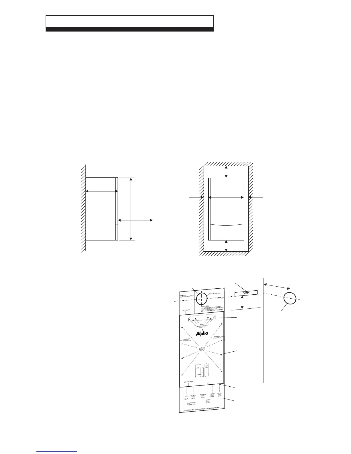
4.2 CLEARANCES REQUIRED - Fig. 10
Fig. 10
4.3 PREPARE THE WALL - Figs. 11
If the optional wall jig is used refer to the
instructions supplied with the kit.
1. Decide upon the position of the boiler taking
into account the clearances required for
servicing and the flue terminal position.
2. Tape the template to the wall (ensure it is
level and the right way up) and mark the
position of the holes for the boiler
mounting bracket or, if applicable the wall
jig fixings. If rear exit flue is used, mark the
position of the hole for the flue.
The wall jig is supplied with a pressure
relief valve discharge pipe for use when
the boiler is mounted on an external wall
where the outside is inaccessible, if you
wish to use this pipe - mark it's position.
3. Side exit flue - Continue the horizontal
centre line of the flue across the wall to the
side wall, then along the side wall 140 mm,
180 mm if the wall jig is used (ensure the
lines are horizontal). This will give the position
of the centre of the hole for the flue.
Fig. 11
720 mm
300 mm
Minimum
clearance
of 450 mm
from front
of boiler
440 mm
235 mm
250 mm
5mm 5mm
Boiler
Minimum
clearances
(340 mm if
wall jig
fitted)
Template
Outline of
boiler
Wall
mounting
bracket
fixing holes
Wall jig
fixing holes
140 mm
(180 mm if wall jig used)
Ensure line is level
Rear exit hole
110 mm dia.
Position of
110 mm hole
to be cut for
side exit flue
145 mm
=
=