15
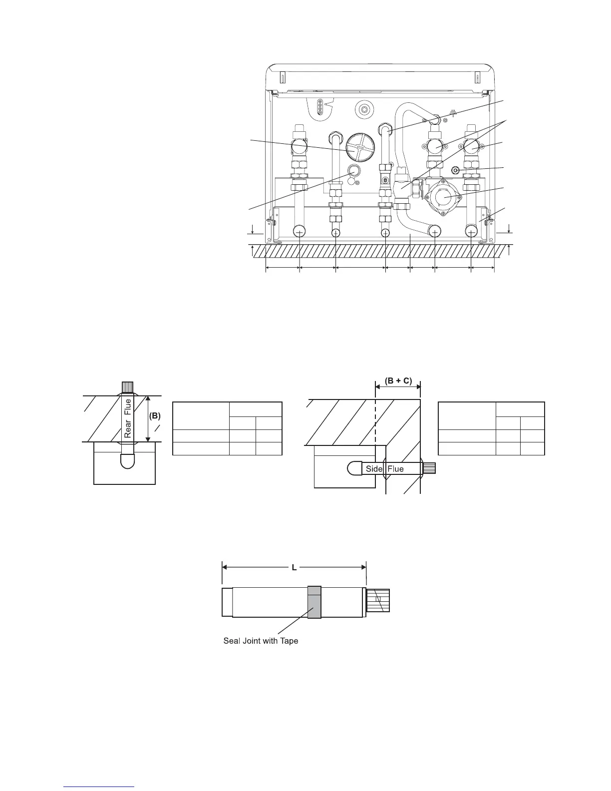
2. Determine the overall length (L) of flue required, (see Fig. 16) as follows:-
Rear flue L = wall thickness (B) + 60 mm
Side flue L = wall thickness (B) + distance between boiler and wall (C) + 120 mm
Fig. 16
3. Adjust the telescopic section of the flue to the distance 'L', ensuring that the two labels marked 'TOP' are aligned, then seal
and secure the joint between the ducts with the sealing tape supplied.
4. Pass the flue assembly through the wall (from inside or outside).
Note: Internal fitting - If there is no access to make good the outside wall, locate the flue sealing collar onto the outer duct
of the flue immediately before the terminal grille onto the location provided. Push the flue assembly through the 130 mm flue
hole, so that the collar completely passes through the wall. Then pull the flue assembly back into the correct position. Visually
check that the collar is sealing the outside wall and that it is not restricting any of the openings of the flue terminal.
4.6 FIT THE FLUE - Figs. 14, 15
The following procedure applies to fitting an Alpha CD Easy-Flue to both rear or side exit flue - horizontally only.
1. The CD Easy-Flues are suitable for use in the flue length ranges shown in the tables below.
Note: Where the length is less than the minimum or more than the maximum, refer to Section 4.7.
Alpha CD25X/28X - Installation
Fig. 14 Fig. 15
CD Easy-Flue
500 mm
1000 mm
B (mm)
Max
550
945
Min
310
705
CD Easy-Flue
500 mm
1000 mm
Max
465
860
Min
225
620
B + C (mm)
Note: Add 40 mm to
dimension B if the wall jig is
used.
Fig. 13b - With wall jig
A - Heating flow (22 mm)
B - Hot water outlet (15 mm)
C - Gas inlet (22 mm)
D - Cold water mains inlet (15 mm)
E - Heating return (22 mm)
F - Pressure relief valve (15 mm)