27
8.12 TERMINAL BLOCK FUSE - Refer to Figs. 20 and 29
The fuse is located in the boiler terminal block.
1. Gain access as described in Installation, Section 4.8.
2. Lift out the fuse holder and remove the fuse. Fit a fast blow 2 A fuse as a replacement, ensuring that the holder snaps into position.
Note: A spare fuse is supplied in the terminal compartment.
3. Re-assemble in reverse order, ensuring the terminal block is located correctly on the plastic pins.
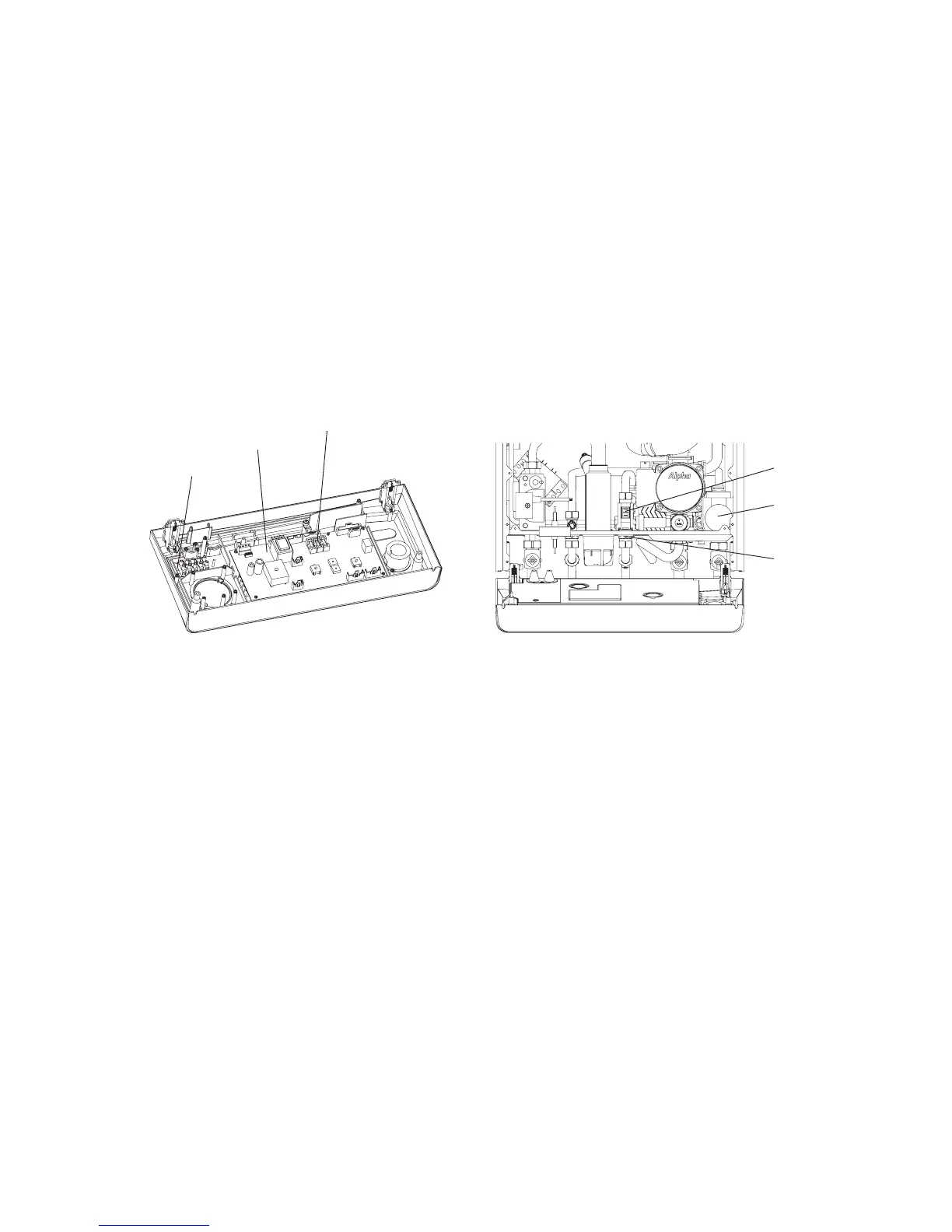
8.13 PCB - Fig. 29
1. Gain access behind the control panel as described in Section 8.1.
2. Disconnect all the wiring connectors from the PCB.
3. Remove the four fixing screws and carefully withdraw the board from the switch spindles.
4. Re-assemble in reverse order. Refer to the wiring diagram in Section 9.1 for connections.
5. Light the boiler and adjust the PCB as described in the instructions supplied with the replacement PCB.
Alpha CD25X/28X - Component Replacement
8.14 DIVERTER VALVE MOTOR - Fig. 30
1. Gain access behind the front casing as described in Section 8.1.
2. Remove the diverter valve motor head by unplugging its electrical connection and removing the retaining clip from the
back of the motor.
3. Withdraw the motor forwards from the valve body.
4. Re-assemble in reverse order with a new motor.
8.15 CLOCK (if fitted) - Refer to Fig. 21
Note: For replacement only use an Alpha single channel clock. Do not fit a two channel clock.
1. Gain access behind the control panel as described in Section 8.1.
2. Remove the two screws securing the clock cover at the rear of the control panel.
3. Disconnect the wiring from the clock.
4. Remove the clock retaining screws and withdraw the clock from the control panel.
5. Fit the new clock, and connect the wires as follows:-
Blue to terminal 1, Brown to terminal 2 and Red wires to terminals 3 and 4, (or as per the instructions supplied with the clock).
6. Re-assemble in reverse order. Refer to the User's instructions and the boiler's control cover to set the clock.
8.16 HEAT EXCHANGER THERMAL FUSE
Note: If the thermal fuse has failed or operated, the heat exchanger must be replaced. Do not attempt to remove the thermal
fuse. Disturbing the sealant securing the thermal fuse will invalidate the warranty.
1. Gain access behind the front casing as described in Section 8.1.
2. Disconnect the wire from the thermal fuse and remove the heat exchanger as described in Section 8.18.
3. Fit a new heat exchanger and re-assemble in reverse order.
Fig. 29
Fig. 30
Terminal block fuse
PCB fuses
PCB