5
Alpha CD25X/28X - Technical Data
Fig. 1
2.8 FLUE LENGTHS
CD Easy-Flue 500 mm with terminal and 90° bend. A CD Easy-Flue 1000 mm with terminal and 90° bend is also available.
CD 750 mm and 1000 mm flue extensions are available.
Length of Flue Required:-
Rear Flue = wall thickness + 140 mm (includes terminal). This is without back frame, add 40 mm if the wall jig is used.
Side Flue = wall thickness + distance between wall and side of boiler + 225 mm (includes terminal)
Vertical Flue = distance from top of boiler side panel to required roof position minus 1000 mm for vertical terminal assembly
Maximum horizontal flue length = 12 m.
Maximum vertical flue length including terminal is 15 m.
Each additional CD 90° Bend is equivalent to 1.3 m of flue length.
Each CD 45° Bend is equivalent to 0.9 m of flue length.
The CD Vertical Flue terminal assembly is equivalent to 1 m of flue length.
2.9 AVAILABLE PUMP HEAD FOR CENTRAL HEATING
gal/min
3.7
2.8
2.3
1.8
0.7
Btu/h
86 700
64 000
53 000
42 200
18 100
kW
25.40
18.70
15.60
12.35
5.30
Output (50/30°C) Available pump head
metres
2.3
3.5
3.8
4.0
4.6
feet
7.6
11.6
12.6
13.2
15.2
litre/min
16.6
12.6
10.5
8.3
3.2
20°C 20°C
Flow rate
This information is based on 20°C system design temperature difference.
Note: For outputs upto 28 kW refer to Section 3.7.
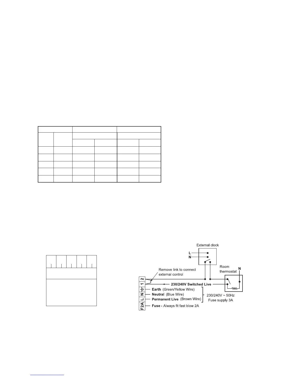
2.10 ELECTRICAL CONNECTIONS
Note: This Appliance Must Be Earthed
An optional integral single channel Clock kit is available if required.
Note: Only use the Alpha single channel clock. Do not fit any two channel clocks.
Boiler terminal block
Clock connections
1. Ensure wires are connected
correctly
2. Only fit the Alpha recommended
single channel clock. Other
clocks could cause damage.
WARNING
Blue
Wire
Brown
Wire
Red
Wire
12345
Internal Clock Terminals
Red
Wire
Not
Used