14
4. Cut the 110 mm diameter hole (or use a 107 mm core drill) in the wall for the flue.
Notes: 1. Ensure the hole is horizontal.
2. For internal fitting of the flue, using the flue sealing collar supplied, cut a 130 mm dia. flue hole using a 127 mm
core drill.
5. Drill the fixing holes (10 mm dia.) to accept the No.10 plugs supplied. Using the screws supplied, fit the mounting bracket or
wall jig if used. If applicable drill a 22 mm dia. hole for the pressure relief valve discharge pipe terminal supplied with the jig.
IMPORTANT: If the wall jig is used, follow the instructions supplied with the Premier Pack to fit the jig,
mount the boiler and connect the pipework.
4.4 FIT THE BOILER - Refer to Fig. 11, 12
1. Lift the boiler and locate it on the mounting bracket.
4.5 CONNECT THE PIPEWORK - Fig. 13
1. Thoroughly flush out all the water pipework. Refer to Section 3.9.
2. The valves/fittings have been factory fitted, however, check that all the
connections underneath the boiler have been tightened, especially the
union bends.
Note: If applicable the heating union bends supplied with the wall jig have
been designed to enable the heating pipes to be routed from above and/
or below using the same fitting.
Note: When soldering to the boiler union bends, ensure the bends are
not connected to the valves, otherwise the internal seals may be
damaged.
3. Connect the system pipework to the boiler.
Note: Do not forget that the pressure relief valve discharge pipe must be
routed clear of the boiler to a drain in such a manner that it may be seen,
but cannot cause injury to persons or property.
4. Connect the 22 mm condensate trap drain pipe to the condensate
discharge pipe using the clip supplied.
Ensure that the condensate discharge pipe is as required in Section 3.10.
Pour at least 0.5 litre of water into the flue duct, as shown in Fig. 12, and check the condensate discharge pipe for soundness.
5. Ensure that all the valves are closed (spindle flats at right angles to valve) and do not turn on the water or gas supplies at this stage.
Alpha CD25C/28C/35C - Installation
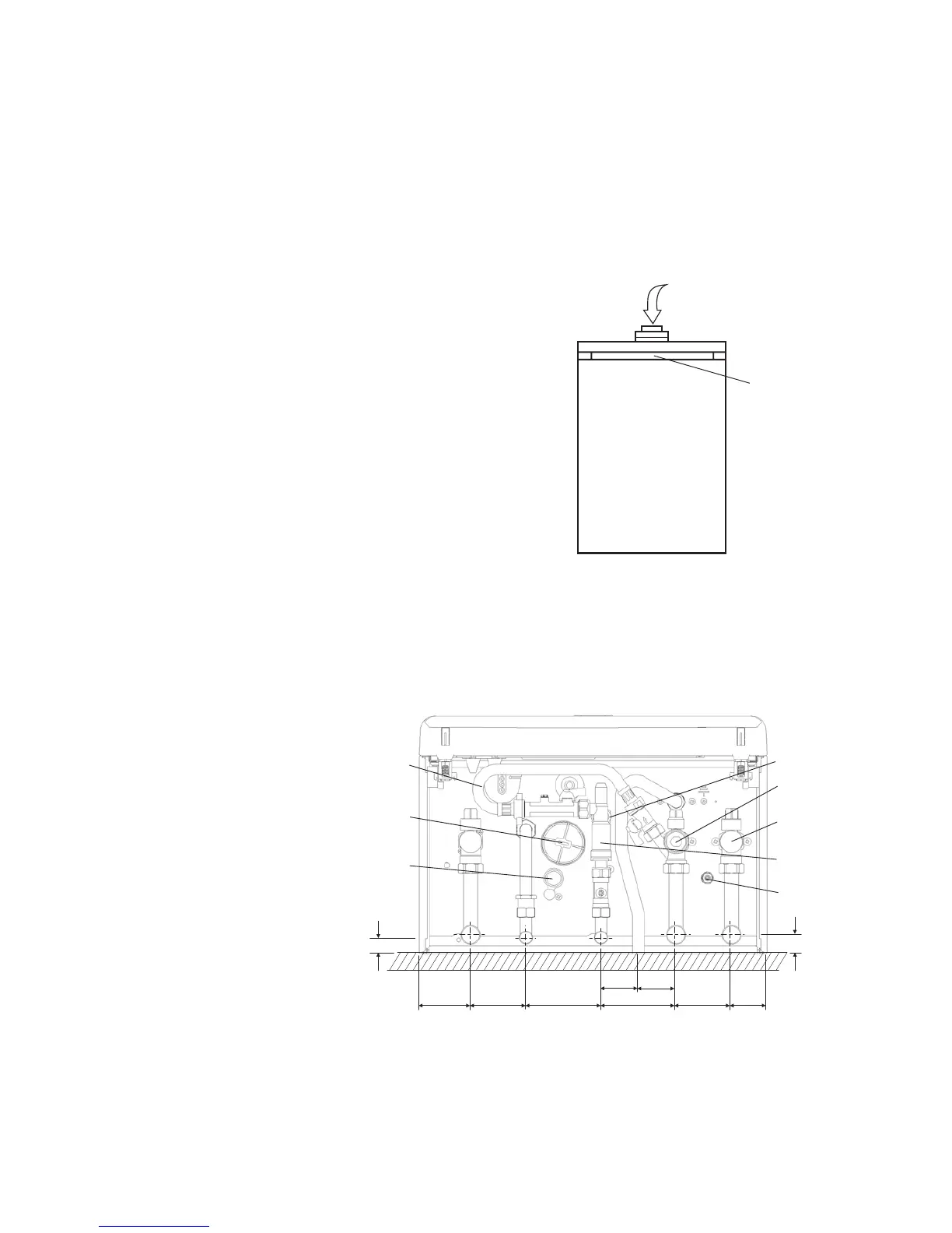
Fig. 12 - rear of boiler
Location for
wall mounting
bracket on
rear of boiler
Pour water into flue duct
Fig. 13a - Without wall jig
A - Heating flow (22 mm)
B - Hot water outlet (15 mm)
C - Gas inlet (22 mm)
D - Cold water mains inlet (15 mm)
E - Heating return (22 mm)
F - Pressure relief valve (15 mm)
G- Heating drain point
H - Cold water inlet filter
I - Condensate discharge pipe
Note: Disconnect the filling loop after
filling the central heating system.
Heating return
valve
Filling loop
G
H
Condensate
trap
20
23
65 70 95 95 70 45
CB DFEA
Heating flow
valve
I
37 58
Seasonality
valve