6
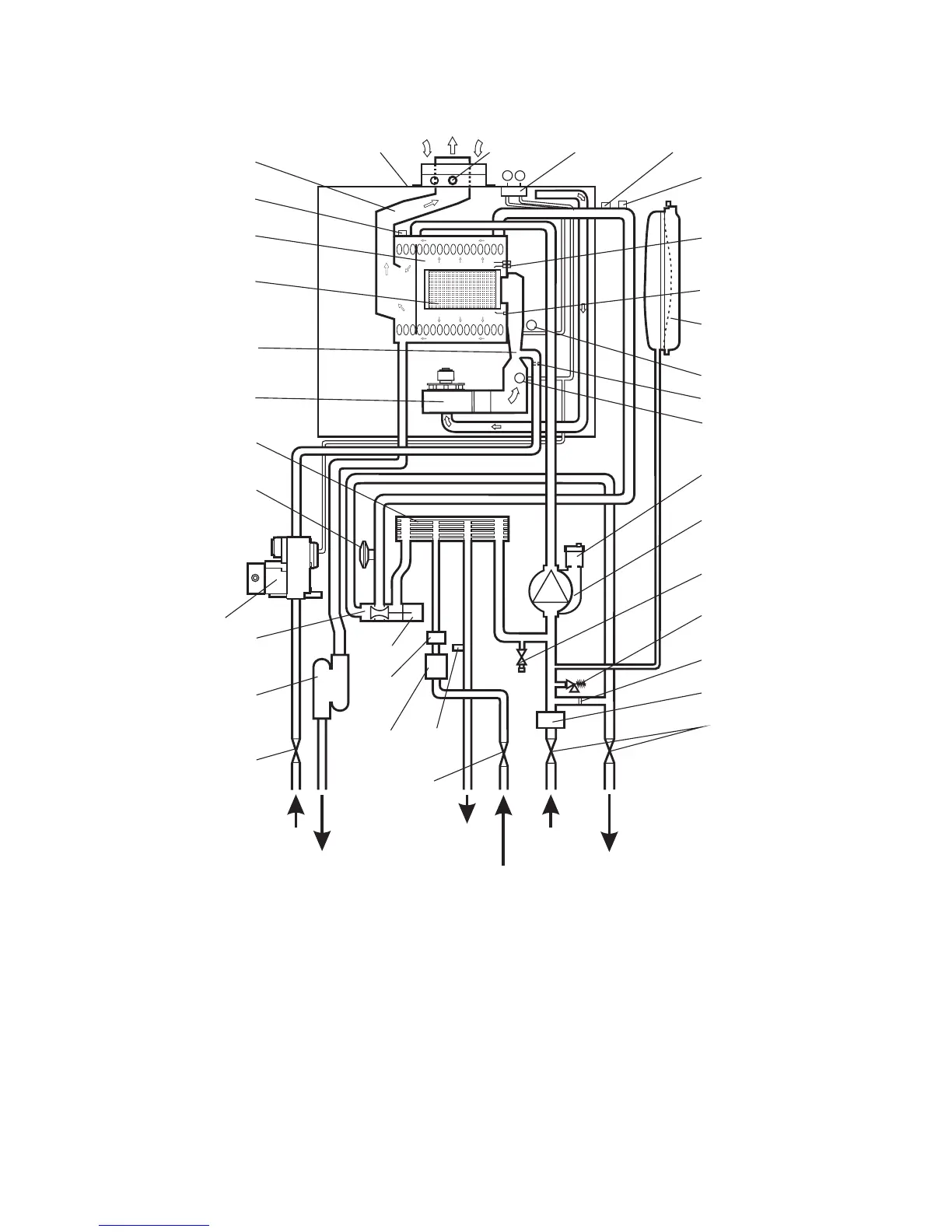
2.11 BOILER SCHEMATIC
1 - Seasonality valve
2 - DHW flow switch and filter
3 - Diverter valve
4 - Gas valve
5 - Primary temperature sensor
6 - DHW heat exchanger
7 - Main burner
8 - Primary/condensing heat exchanger
9 - Room sealed chamber
10 - Fan
11 - Pressure differential test points
12 - Flue hood
Fig. 2
13 - Overheat thermostat
14 - Expansion vessel
15 - Automatic air vent
16 - Pump
17 - Drain point
18 - Pressure relief valve
19 - Primary pressure switch
20 - Ignition electrodes
21 - Flame sensing electrode
22 - DHW temperature sensor
23 - Flue sampling point
24 - Gas service cock
25 - Mains inlet on/off valve
26 - On/off valve (2 off)
27 - Automatic by-pass
28 - Cyclone separator (if applicable)
29 - Condensate trap
30 - Injector
31 - Venturi
32 - Venturi negative point
33 - Venturi positive point
34 - Flue thermostat
35 - Diverter valve motor
Alpha CD25C/28C/35C - Technical Data
Gas
Condensate
discharge
Primary
Heating
return
Primary
Heating
flow
24
4
23
-
-
+
+
9
10
29
35
11
34
5
13
20
14
32
33
15
16
17
18
27
28
26
Domestic
hot water
outlet
Cold mains
water inlet
1
2
3
6
19
22
25
12
8
7
21
31
30