4.
1.
2. 3.
5.
EN DE FR
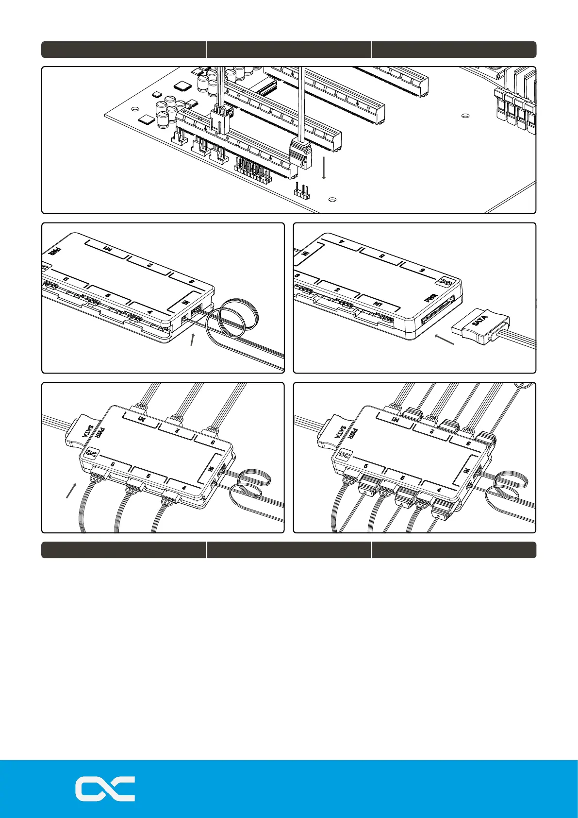
1. Connect the 2 pin aRGB and 4 pin PWM
cable to your motherboard aRGB/4pin fan
output, ensure the aRBG output is a 3 pin
terminal, and not 4 pin, as damage can result
of improper connection.
2. Connect the 2 pin aRGB IN and 4 pin PWM
plug to the controller.
3. Connect the SATA power plug from your
power supply to the SATA power input of the
controller. Ensure power is OFF during this
process.
4. Connect the 4 pin fans to the relevent
sockets (OUT). Socket M1 is the tacho signal
and must be populated rst.
5. Connect the 3 pin aRBG connectors to the
relevent sockets
A maximum power consumption of 22.5W
(4.5A) can be drawn from the controller.
1. Schließen Sie das 2-polige aRGB- und das
4-polige PWM-Kabel an den aRGB/4-poligen
Lüfterausgang Ihres Motherboards an.
Achten Sie darauf, dass der aRBG-Ausgang
ein 3-poliger Anschluss ist und nicht ein 4-
poliger, da eine unsachgemäße Verbindung
zu Schäden führen kann.
2. Verbinden Sie den 2-Pin Stecker mit dem
Controller (IN).
3. Schließen Sie den SATA-Strom Stecker
ihres Netzteils an die Buchse (PWR) des
Controller an. Stellen Sie sicher, dass die
Stromversorgung beim Vorgang
ausgeschaltet ist.
4. Schließen Sie die 4-poligen Lüfter an die
entsprechenden Buchsen (OUT) an. Die
Buchse M1 ist das Tachosignal und muss
zuerst bestückt werden.
5. Verbinden Sie die 3-poligen aRBG-Stecker
mit den entsprechenden Buchsen
Die maximale Leistungsaufnahme des
Controllers beträgt 22,5 W (4,5 A).
1. Connectez le câble aRGB à 2 broches et le
câble PWM à 4 broches à la sortie ventilateur
aRGB/4 broches de votre carte mère.
Assurez-vous que la sortie aRBG est une
borne à 3 broches, et non à 4 broches, car
une connexion incorrecte peut entraîner des
dommages.
2. Connectez la che 2 pin aRGB IN et 4 pin
PWM au contrôleur.
3. Branchez la che d'alimentation SATA de
votre bloc d'alimentation à la prise (PWR) du
contrôleur. Veillez à ce que l'alimentation soit
coupée pendant l'opération.
4. Connectez les ventilateurs à 4 broches aux
prises correspondantes (OUT). La prise M1
est le signal tachymétrique et doit être
remplie en premier.
5. Connectez les connecteurs ARBG à 3
broches aux prises correspondantes.
Le contrôleur peut consommer une puissance
maximale de 22,5 W (4,5 A).
GENERAL MANAGERS: ANDREAS RUDNICKI, FABIAN
NOELTE
WEEE-REG.-NR.: DE 54464644
TRADE REGISTER: AMTSGERICHT BRAUNSCHWEIG HRB
202390
VAT.ID.NR.: DE270458421
TAX NUMBER: 13/207/02047
V.1.00-07.2022
ALPHACOOL INTERNATIONAL
GMBH
MARIENBERGER STR. 1
D-38122 BRAUNSCHWEIG
GERMANY
SUPPORT: +49 (0) 531 28874 - 0
FAX: +49 (0) 531 28874 - 22
E-MAIL:
INFO@ALPHACOOL.COM
HTTPS://
WWW.ALPHACOOL.COM
Connect the cable Kabel anschließen Brancher le câble
 Loading...