4
HOW TO INSTALL BASE
EXISTING DECKING
1. Position base plate in desired location, square off and make sure it’s level.
2. Mark holes into the decking using the outer pre-drilled holes in the surface plate as guides.
3. Remove surrounding decking - leave decking under surface plate.
4. Measure the distance between joists and cut the nogs to suit. It requires a minimum depth of 200mm (A) and
a minimum width of 400mm (D). We suggest using 200x50mm timber framing and secured as illustrated in
the diagrams below.
5. Secure these under the desired location for the surface plate using 14G X 150MM (min) bugle screws (not
included). Decks with joists thicker than 75mm will require longer bugle screws. Pre-drilling is recommended.
6. Using your previous marks, drill through the decking and the newly installed nogs.
7. Level and secure the surface plate using M12 bolts/threaded rod, washers and nylon nuts.
8. Replace the decking
9. Once the surface plate is secured to the reinforced decking follow the ‘INSTALLING THE SPIGOT TO
SURFACE PLATE’ instructions (page 9) to attach the ‘spigot’ to the ‘surface plate’.
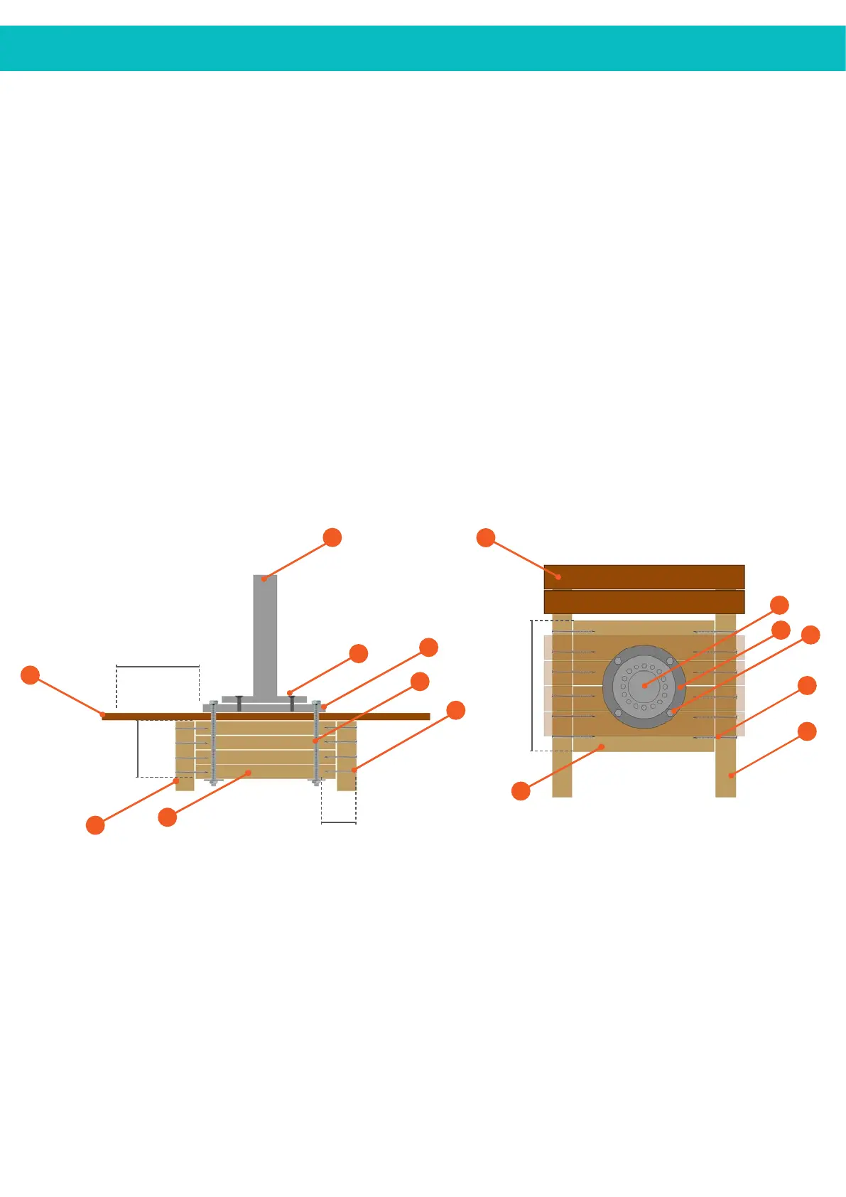
1 ................................................................................ SPIGOT
2 ............................................................ SURFACE PLATE
3 ..................................... M12 THREADED ROD/BOLT,
SQUARE WASHER & NUT
4 ............................................................................ DECKING
5 ....................... COUNTERSUNK HEX BOLT 25MM
6 ..................... 14G X 150MM (min) BUGLE SCREW
7 .................................................................................... JOIST
8 ....................................................................................... NOG
200MM (min) NOG DEPTH ....................................... A
300MM OFF WALL OR FENCE .............................. B
150MM (min) DEEP SCREW ..................................... C
400MM (min) WIDE NOG .......................................... D
1.
A = 200mm
B = 300mm
D = 400mm
(MIN)
(MIN)
(MIN)
2.
3.
5.
7.
7.
8.
4.
6.
Drawings are not to scale
Gaps in drawing are for illustration purposes only
TOP VIEW SIDE VIEW
C = 150mm
(MIN)
1.
2.
3.
4.
8.
6.
 Loading...