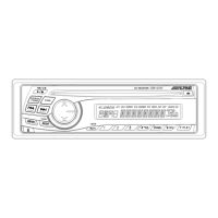
CDE-9841/CDE-9841E
No. Symbol I/O Terminal Description
52 IN INT(NC) - No connect terminal.
53 P-ANT O External Power ANT control signal output terminal.
54
I
58
59 ELE VOL-DATA I/O E-VOL DATA input / output terminal.
60 VCC - Power supply connect terminal.
61 ELE VOL-CLK O E-VOL CLOCK output terminal.
62 VSS - GND connect terminal.
63 LAMP ON O Lighting power supply control output terminal.
64 IF MUTE O IF MUTE signal output terminal.
65 NC - No connect terminal.
66 MOD SEL I Destination switching input terminal.
67
I
73
74 CONT1
75 CONT2
76
77
78 TU SCL O Serial clock output terminal to TUNER.
79 TU SDA I/O Serial data input / output terminal to TUNER.
80 NC - No connect terminal.
81 ST I ST signal input terminal.
82 NC
83 DAVN(NC)
84 NC
85 RDS SDA(NC)
86 RDS SCL(NC)
87 HI TEMP I CD HI-TEMP input terminal.
88 NC
89 M/P(NC)
90 S/M I TUNER S/M level input terminal.
91 SD I SD signal input terminal.
92 KEY2
93 KEY1
94 AVSS - GND connect terminal for A/D Converter.
95 NOSE DET I NOSE installation detect terminal.
96 VREF - Reference voltage input terminal for A/D Converter.
97 AVCC - Power supply connect terminal for A/D Converter.
98 LCD ON O LCD back-lighting control terminal.
99 LCD DO O Data output terminal to LCD Driver.
100 LCD CLK O Clock output terminal to LCD Driver.
KEY signal input terminal.I
O System Power IC (HA13165) control signal output terminal.
- No connect terminal.
- No connect terminal.
NC - No connect terminal.
NC
NC
- No connect terminal.
No connect terminal.-