Do you have a question about the Alpine CTA-1505R and is the answer not in the manual?
Lists all parts included in the product packaging.
Illustrates the physical arrangement of components during packing.
Technical details for the FM reception band.
Technical details for the MW reception band.
Technical details for the LW reception band.
Overall electrical and physical characteristics of the device.
Step-by-step guide for tuning and calibrating FM/AM circuits.
Specifies initial settings for controls before performing adjustments.
Detailed steps for signal meter, IF, distortion, and separation adjustments.
Identifies physical locations of adjustment components on the tuner unit.
Overview of internal signal paths and component interactions.
Comprehensive electrical schematic of the tuner section.
Component placement on the main printed circuit board.
Foil side component placement on the main printed circuit board.
Component placement on the audio printed circuit board.
Component placement on the front panel printed circuit board.
Schematic detailing the audio selector and E-VOL functions.
Schematic for the power amplifier and associated buffer stages.
Schematic of the DC-DC converter and remote control interface.
Schematic for the equalizer and BBE sound enhancement circuits.
Schematic of the front panel controls and displays.
Detailed pin functions for IC501.
Detailed pin functions for IC502.
Pin functions for various other ICs in the system.
List of components on the main P.W. Board, including ICs, transistors, diodes, and coils.
Comprehensive list of all capacitors used in the device with their specifications.
Comprehensive list of all resistors used in the device with their specifications.
Lists of diodes and transistors with part numbers and descriptions.
List of components on the front P.W. Board, including lamps, LEDs, switches, and ICs.
List of components for the DC-DC converter section.
List of front panel switches, indicator lamps, and LEDs.
Lists various connectors, coils, transformers, and miscellaneous parts.
Visual breakdown of the device's physical cabinet structure and components.
Step-by-step guide for safely disassembling the device's cabinet.
Detailed pin functions for IC501.
Detailed pin functions for IC502.
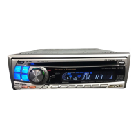
| Maximum Power | 50W x 4 |
|---|---|
| Power Output | 22W RMS x 4 |
| Preamp Voltage | 2V |
| Button Illumination | Red |
| Audio Formats | MP3/WMA/AAC |
| USB Input | Yes |
| AUX Input | Yes |
| Built-in Bluetooth | No |
| USB Port | Yes |
| Auxiliary Input | Yes |
| Display | LCD |
| Remote Control | Yes |
| Radio Tuner | AM/FM |
| MP3 Playback | Yes |
| WMA Playback | Yes |
| AAC Playback | Yes |
| Preamp Outputs | 2 |