Home
Alpine
Monitor
PKG-1000
Page 21
Alpine PKG-1000 - Page 21
61 pages
Manual
Save Page as PDF
To Next Page
To Next Page
To Previous Page
To Previous Page
Loading...
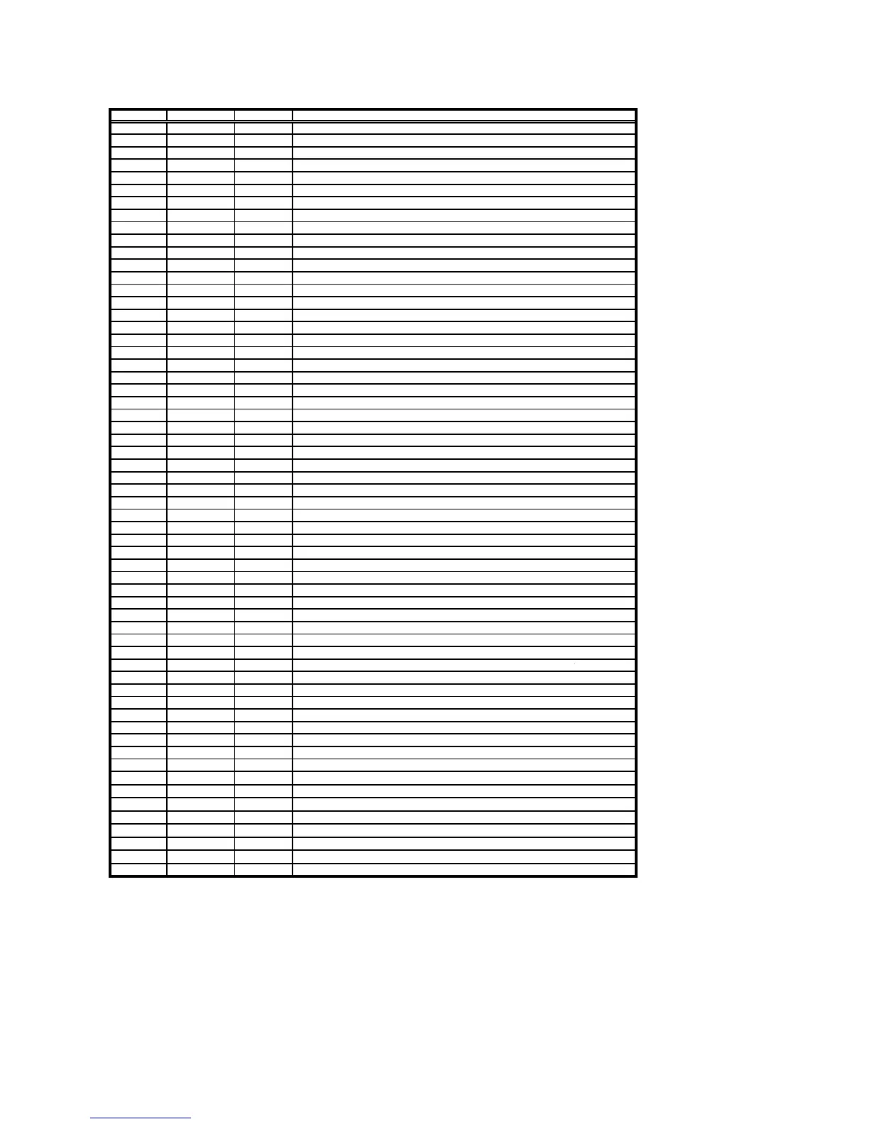
Descri
p
tion of AU Panel Pin Assi
g
nmen
t
Pin
Name
T
yp
e
Function Descri
p
tion
1
POL
O
Polarit
y
selection
2
DIO 2
I/O
Vertical start
p
ulse si
g
nal in
p
ut or out
pu
3
OE
I
Out
p
ut enabl
e
4C
P
V
I
vertical cloc
k
5
DIO 1
I
Vertical start
p
ulse si
g
nal in
p
ut or out
pu
6
GND
I
Power
g
roun
d
7
EDGSL
I
Select risin
g
ed
g
e or risin
g
/fallin
g
ed
g
8
VCC
I
Di
g
ital volta
g
e for source drive
r
9
V9
I
Gam ma volta
g
e level
9
10
VG
L
I
Gate OFF volta
ge
11
V2
I
Gam ma volta
g
e level
2
12
VGH
I
Gate ON volta
ge
13
V6
I
Gam ma volta
g
e level 6
14
U/D
I
U
p
/down selectio
n
15
VCOM 1
I
Common volta
ge
16
GND
I
Power
g
roun
d
17
AVDD1
I
Power su
pp
l
y
for analo
g
circui
f
18
V14
I
Gam ma volta
g
e level 1
4
19
V11
I
Gam ma volta
g
e level 1
1
20
V8
I
Gam ma volta
g
e level
8
21
V5
I
Gam ma volta
g
e level
5
22
V3
I
Gam ma volta
g
e level
3
23
GND
I
Power
g
roun
d
24
R5
I
Red data
(
MSB
)
25
R4
I
Red dat
a
26
R3
I
Red dat
a
27
R2
I
Red dat
a
28
R1
I
Red dat
a
29
R0
I
Red data
(
LSB
)
30
GND
I
Power
g
roun
d
31
GND
I
Power
g
roun
d
32
G5
I
Green data
(
MSB
)
33
G4
I
Green dat
a
34
G3
I
Green dat
a
35
G2
I
Green dat
a
36
G1
I
Green dat
a
37
G0
I
Green data
(
LSB
)
38
STHL
I/O
Horizontal start
p
ulse si
g
nal in
p
ut or out
pu
39
IN
V
I
Control si
g
nal are inverted b
y
ASIC or n
o
40
GND
I
Power
g
roun
d
41
DCL
K
I
Sam
p
le cloc
k
42
DVDD
I
Volta
g
e for di
g
ital circui
t
43
STHR
I/O
Horizontal start
p
ulse si
g
nal in
p
ut or out
pu
44
LD
I
Latches the
p
olarit
y
of out
p
uts and switches the new data to out
p
u
t
45
B5
I
Blue data
(
MSB
)
46
B4
I
Blue dat
a
47
B3
I
Blue dat
a
48
B2
I
Blue dat
a
49
B1
I
Blue dat
a
50
B0
I
Blue data
(
LSB
)
51
R/L
I
Ri
g
ht left selectio
n
52
V1
I
Gam ma volta
g
e level
1
53
V4
I
Gam ma voltage level 4
54
V7
I
Gam ma voltage level 7
55
V10
I
Gam ma voltage level 10
56
V12
I
Gam ma voltage level 12
57
V13
I
Gam ma voltage level 13
58
AVDD2
I
Voltage for analog circuit
59
GND
I
Power ground
60
VCOM2
I
Common voltage
20
22
Table of Contents
Main Page
Service Manual
1
Table of Contents
4
Features
5
System Connections
6
Adjustment Procedures
7
Block Diagram
15
IC Voltage Chart
16
IC Terminal Descriptions
18
Electronic Component Parts List
22
Key Board
25
Mechanical Component Parts List
30
Decoder
31
Inverter
32
Panel
33
DC to DC & GAMMA
34
Mcu
36
Scan
37
Power Regulator
38
Power Board Schematic Diagram 1. Power Input
39
Audio
40
Mcu
41
FM Transmitter
42
Key Board Schematic Diagram
43
IR Board Schematic Diagram
44
Lamp Board Schematic Diagram
45
Slim Box Switch Schematic Diagram
46
Slim Box Control Schematic Diagram
47
Parts Layout and Wiring Diagrams 1~3
48
Packing Materials and Contents Exploded View
51
Cabinet Exploded View
55
Sub-Assembly 1~4 Exploded View
56
Sub-Assembly 5~7 Exploded View
57
Sub-Assembly 8~10 Exploded View
58
Sub-Assembly 11~15 Exploded View
59
Customer Registration Card
60
Related product manuals
Alpine PKG-RSE2
36 pages
Alpine TMX-R705
22 pages
Alpine TME-M760
8 pages
Alpine RearVision TMX-R3200SE
21 pages
Alpine TME-M680
13 pages