Do you have a question about the Alpine SPX-Z18T and is the answer not in the manual?
Explains warning and caution symbols used in the manual for safety instructions.
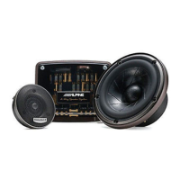
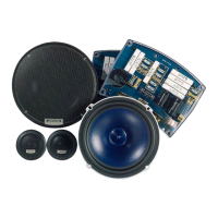
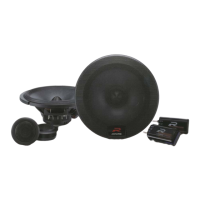
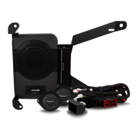
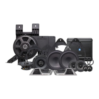
Lists all components and hardware associated with the woofer unit.
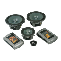
Lists all components and hardware associated with the midrange unit.
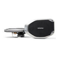
Lists all components and hardware associated with the tweeter unit.
Lists the crossover network components and associated items.
Details the process of installing the woofer without its protective grille.
Details the process of installing the woofer with its protective grille attached.
Details the process of installing the woofer using adapter rings.
Details the process of installing the midrange without its protective grille.
Details the process of installing the midrange with its protective grille attached.
Details the installation of the tweeter using springs for mounting.
Details the front-mount installation of the tweeter using a mounting cup.
Details the installation of the tweeter using fastening rings.
Illustrates single amplifier/single wiring connections for the network.
Illustrates bi-amplifier/bi-wiring connections for the network.
Illustrates tri-amplifier/tri-wiring connections for the network.
Explains the tweeter high-pass filter function and jumper settings for integration.
Explains the tweeter level adjustment function and its effect on frequency response.
Details the low-pass filter adjustments for the woofer and system integration.
Describes the favorable configuration with drivers equidistant to the listening position.
Describes a variation for off-axis listening angles due to mounting surface orientation.
Details jumper settings for Type-1A, assuming on-axis positioning and equal pathlength.
Details jumper settings for Type-1B, accommodating off-axis listening and higher output.
Describes driver mounting flush to a flat vertical surface with varying angles and distances.
Describes mounting where the woofer is farther forward, resulting in extreme listening angles.
Details jumper settings for Type-2A, considering specific pathlengths and angles for optimal integration.
Details jumper settings for Type-2B, adjusting for woofer placement and listener angles.
Describes midrange and tweeter close together, woofer mounted separately, minimizing off-axis angle.
Describes tweeter and midrange flush to panel with minimal build-out, resulting in off-axis conditions.
Details jumper settings for Type-3A, considering driver distances and angles for summation points.
Details jumper settings for Type-3B, accounting for midrange orientation and woofer proximity.
Describes using the network in a partially active mode with external signal processing.
Explains the +4dB/30° setting bypasses all resistors in the tweeter section.
Provides detailed measurements and diagrams for the woofer unit.
Provides detailed measurements and diagrams for the midrange unit.
Details overall system type, power handling, impedance, and frequency response.
Lists general, mechanical, and Thiele/Small parameters for woofer, midrange, and tweeter.
| Speaker Size | 6.5 inches |
|---|---|
| Power Handling (Peak) | 300 Watts |
| Power Handling (RMS) | 100 Watts |
| Impedance | 4 Ohms |
| Type | Component |
| Sensitivity | 88 dB |