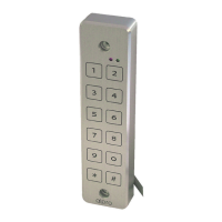
Waterproof Keypad
AS626S
Read all instructions before starting installation
Connect keypad using wiring description.
Wiring description
Power 12 or 24v AC or DC
(AC does not have a polarity)
Brown + Positive
Blue - Negative
Output Relay Max 2amp @ 24v
Grey Common
Red Selectable – Relay NO or NC (Default is set to NO)
To change see 7 & 8 under ‘Programming the Keypad’
Contact 2 Amp. Dry contact for Door Strike
Exit Button Push to make – Volt free
White/Pink Exit Button (NO)
Power Consumption Stand by – Approximately 25 milliamps @12vDC
Operation – Approximately 80 milliamps @12vDC
For 12vDC inductive loads such as electric strikes and electromagnetic locks,
the enclosed 12vDC metal oxide varistor must be connected in parallel with
the load, at the load terminals and not in the keypad.
Ensure power supply is of correct rating, taking into account the current
requirements of the locking items and accessories.
Do not insert security plugs into fixing holes until all installation and testing has
been completed. These items require drilling out and cannot be re-fitted.
LED signalling explanation
GREEN LED Door Strike activated (unlocked)
RED LED Normal Operation: 3 sec. ON = wrong
Code Entry
Slow flashing = wrong code
entry 3 times
Programming Mode: Fast flashing = programming
different functions
Slow flashing = programming
stand-by
Very fast flashing = erasing all
user codes
The door remote opening (via exit switch) is possible when a dry contact is
made between the wires White and Orange.
The lock is activated for the time the system is programmed. Factory set @
5 seconds.
Remote opening is disabled during programming and latch mode.
Apply power to the keypad. The keypad’s buzzer will sound briefly, the
Red LED will illuminate briefly Initialisation is now complete, with a default
master code of 1-2-3-4 and a 5-second open door.
PACK CONTENTS
MOUNTING INSTRUCTIONS
ACTIVATION
TESTING THE UNIT
PROGRAMMING THE KEYPAD
TROUBLE SHOOTING
INITIALISATION
Connect to + of
Locking Device
Connect to - of
Locking Device
Breakglass
Pink
White
Brown
Blue
Grey
Red
Power Supply
Exit Button
Enter the master code [1 2 3 4 #]
The Door Relay changes its contacts for 5 sec.
The Green LED will light up for 5 sec. Repeat this step 2,3 times.
If the master code is wrongly typed in, the Red LED lights up for 3 sec. re-
enter the Code as soon as the LED goes OFF.
IMPORTANT: CHANGE THE FACTORY SET MASTER CODE WHEN YOU PROGRAM
YOUR UNIT FOR USE. THERE IS NO WAY TO RECOVER THE NEW MASTER CODE IF
IT IS LOST OR FORGOTTEN. THE UNIT CAN BE RESET TO FACTORY PRESETS AND
CUSTOMISED AGAIN. See Data Reset
Enter H H1 2 3 4 H H
The keypad enters programming mode, the Red LED flashes
If no further information is added, the unit will revert to normal
operation after a 3 second delay. To exit programming press #.
There are six programming options: -
1. Set new master code
It is suggested the Master Code is not changed until person
programming is familiar with all aspects of programming the keypad!
2. Set new user code
3. Erase a user code
4. Erase all user codes
5. Set door open time (1-99s)
6. Set output to latch option
Continued over...
The keypad does not “respond” when activating the keys.
1. Make sure the electronic unit has been properly wired to the PSU and the
power has not been cut-off.
The keypad “responds” but the door does not open.
1. Make sure the Green LED is illuminated.
2. If not, the entered code has not been programmed yet. Please refer to
“Programming”.
3. Enter the Master Code and make sure the door opens correctly. If not,
check the wiring and the Lock’s integrity.
1
3
5
7
9
*
2
4
6
8
0
#
x2x2