EasyManua.ls Logo

Alstom FKG1X - Page 129

Alstom FKG1X
274 pages
To Next Page IconTo Next Page
To Previous Page IconTo Previous Page
Loading...
Installation
Assembly of th
e circuit b
reaker on-
-
site
G31--201EN12
12/20
04--2011
© ALSTOM 2010. All rights reserved. Informat
ion contained in
this document is indicative only. No
representati
on or
warrant
y is
given or should
be
relied on that it is complete or correct or will apply to any particular project. This will depend on the technical and commercial circumstances. It is
provided without liabili
ty and
is subject to
change without notice. Reproduction, use or disclosure to
third parties, without express writt
en authority, is
strictly prohibited.
GRID
Installing
the circuit
-
-
breaker -
-
Step 3
Connections
Carry
out
the
joining
up
of
the
flexible
conne
ctions
as
follows
:
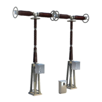
(See VS...GAD01D, ...31--501 and ...31--001)
D
Prep
ar
e
the
co
nta
ct
su
rfa
ce
s
on
the
br
aid
s,
an
d
the
ci
rcu
it
bre
ak
er
co
nn
ec
-
tions.
Refer to the procedure “Connections with preparation of electrical contact
surfaces”
,
see summary
for
referenc
e
(...31-
-501).
D
Assemble the braids, and tighten to torque.
Re
fer
to
the
pr
oc
ed
ur
e
Bo
lti
ng
an
d
tig
hte
nin
g
tor
qu
es
,
se
e
su
mma
ry
for
ref
-
erence (...31--001).
.
A
...
31-
-501
FLEXIBLE CONNECTIONS.
SUPPLY FOLLOWING CUSTOMER
COMMAND(ORDER).
daNm
...
31-
-001
VS...GAD01D
Circuit-breaker
General arrangement
.
A
.
A
VS...GAD01D
Circuit-breaker
General arrangement
SCREWS
SUPPLY FOLLOWING CUSTOMER
COMMAND(ORDER)
Continued on next page.

Related product manuals