Do you have a question about the Alstom GL317X and is the answer not in the manual?
References to product safety sheets, listed under Annexes.
Details on the technical specifications of the circuit-breaker.
Information found on the circuit-breaker's rating plate.
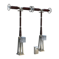
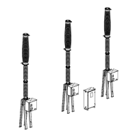
An overview of the circuit-breaker's main components and structure.
Detailed explanation of the interrupting chambers within the circuit-breaker.
Explanation of the mechanism and principle behind pole operation.
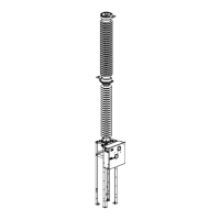
Details on the circuit-breaker's operating mechanism.
Information regarding the monitoring of SF6 gas levels.
Procedures and information for packaging, identification, and storage.
General guidelines for the erection process of the circuit-breaker.
Specified torque values for tightening components during installation.
Standard procedures for the erection of the circuit-breaker.
Procedure to check for nitrogen presence in the pole components.
Instructions for assembling the supporting frame.
Steps for coupling the column with the circuit-breaker chambers.
Procedure for tipping down the pole and related vacuum operations.
Guidance on installing terminals and preparing contact surfaces.
Instructions for installing the capacitors.
Procedure for installing stress-shields on interrupting chambers.
Steps for safely lifting and positioning the circuit-breaker pole.
Instructions for installing the operating device.
Inspections performed before commissioning the equipment.
Format and content for the commissioning test report.
Checklist for commissioning and RPH2 maintenance tasks.
Criteria to be met for acceptance of the commissioned equipment.
Scheduled maintenance plan for the circuit-breaker.
Limits for electrical wear on components.
Inspection of electrical contact thresholds using a densimeter.
Procedures for intervening on the operating device.
List of required tooling and accessories for maintenance and operation.
References and access to product safety data sheets.
Outline drawing of the RPH2 component.
Wiring diagram for the RPH2 component.
Service manual for the RPH2 component.
Checklist for commissioning and maintenance of RPH2.
Procedures for dismantling, recovery, and SF6 gas management.
Instructions for assembling the supporting frame for complementary installation.
Steps for lifting and positioning the pole during complementary installation.
Guidance on installing terminals and preparing contact surfaces.
Instructions for installing capacitors in the complementary procedure.
Procedure for installing stress-shields on interrupting chambers.
Steps for coupling the column with chambers in the complementary procedure.
Instructions for installing the operating device in the complementary procedure.
An overview of the circuit-breaker's main components and structure.
Details of the pole's components: chambers, support column, and mechanism housing.
Description of the support frame that holds the circuit-breaker components.
Description of the spring operating mechanism and its indicators.
Details on the marshalling cubicle, including relays and terminal boards.
Overview of the interrupting chamber parts: chamber and upper housing.
Details on the interrupting chamber's quenching medium and principle.
Description of the upper housing and its internal movement transfer mechanism.
Explanation of current path in closed position and operational stages.
Description of the opening sequence initiated by the spring mechanism.
| Rated Short-Circuit Breaking Current | 25 kA |
|---|---|
| Rated Frequency | 50/60 Hz |
| Rated Short-Time Withstand Current | 25 kA |
| Mechanical Endurance | 10, 000 operations |
| Interrupting Medium | SF6 |