Description and operation
Description of the interrupting chambers
L12--105EN/03
3/4
01--2011
© ALSTOM 2010. All rights reserved. Information contained in this document is indicative only. No representation or warranty is given or should be
relied on that it is complete or correct or will apply to any particular project. This will depend on the technical and commercial circumstances. It is
provided without liability and is subject to change without notice. Reproduction, use or disclosure to third parties, without express written authority, is
strictly prohibited.
GRID
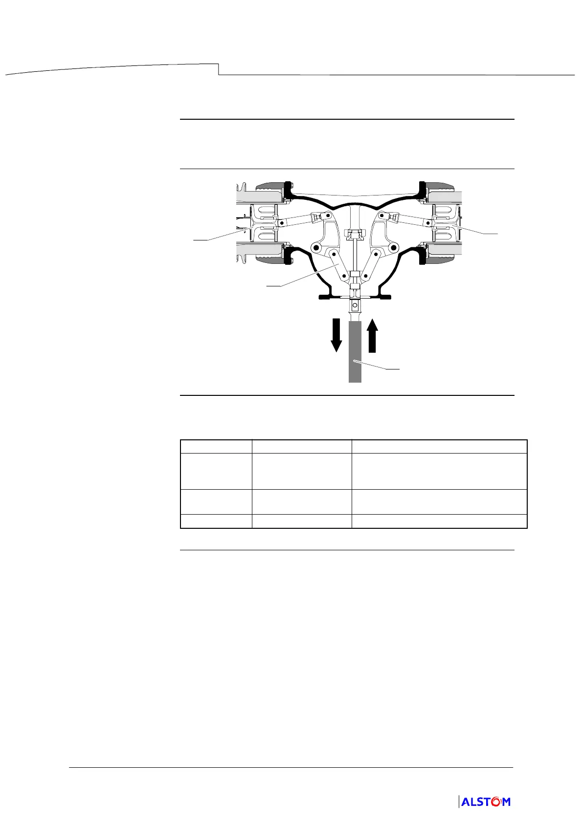
Upper housing
Description
The upper housing encloses the movement transfer mechanism (15) from the
operating tie--rod (8) to the moving contact (4) of the two chambers.
Diagram
15
8
4
4
Parts table
The table below gives the housing internal and peripheral components :
Mark Component Function
(4) Moving contact It is worked by the operating
mechanism and contains the blasting
device.
(8) Operating tie--rod T ransmits the movement to the moving
contact of the two chambers.
(15) Mechanism T ransfer of the movement.
 Loading...