EasyManua.ls Logo

Alstom FKG1X - Page 143

Alstom FKG1X
274 pages
To Next Page IconTo Next Page
To Previous Page IconTo Previous Page
Loading...
Installation
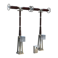
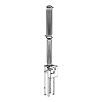
Measuring main circuit resistance
G31
-
-4
01EN02
6/10
02--2011
© ALSTOM 2010. All rights reserved. Informat
ion contained in
this document is indicative only. No
representati
on or
warrant
y is
given or should
be
relied on that it is complete or correct or will apply to any particular project. This will depend on the technical and commercial circumstances. It is
provided without liabili
ty and
is subject to
change without notice. Reproduction, use or disclosure to
third parties, without express writt
en authority, is
strictly prohibited.
GRID
Measuring main resistance
procedure of generato
r circuit
-
-
breaker
Position of
mater
ial
put in posi
tion ”LOCA
L” (manu
al ope
rating mec
hanism
), the oper
ating me
-
chanism,
-
-
circuit-b
reaker and disconnec
tor closed,
-
-
earthing switch
(es) or starting
discon
nector (if applicable) opene
d.
Process
D
Establish a direct current at least 100 A between the input and output of
the apparatus to be tested.
D
Connect the measuring equipment on the holes allowed.
D
Measurement (
R2
) of voltage decrease between these two points gives
the resistance value at the rate of 100
m
V for 1
m
Ω
.
100 A
100 A
R2
Hole
Ø
4
R2
Hole
Ø
4
Reminder
The
resi
stan
ce
on
eac
h
app
ara
tus
mus
t
be
less
than
the
valu
e
giv
en
in
“ACCEPTANCE CRITERIA”.
Refer to the document “ACCEPTANCE CRITERIA”, see summary for refer-
ence.

Related product manuals