EasyManua.ls Logo

Alstom FKG1X - Page 35

Alstom FKG1X
274 pages
To Next Page IconTo Next Page
To Previous Page IconTo Previous Page
Loading...
Description and operation
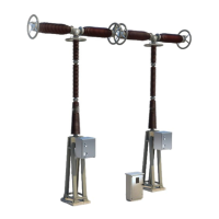
General Description of the Circuit breaker
G12
-
-0
01EN10
2/12
02--2011
© ALSTOM 2010. All rights reserved. Informat
ion contained in
this document is indicative only. No
representati
on or
warrant
y is
given or should
be
relied on that it is complete or correct or will apply to any particular project. This will depend on the technical and commercial circumstances. It is
provided without liabili
ty and
is subject to
change without notice. Reproduction, use or disclosure to
third parties, without express writt
en authority, is
strictly prohibited.
GRID
FKG1XP / XV /
XW Circuit breaker
with FK3
-
-
12 spring
-
-
powered controls
Description
The
equipm
ent
compris
es
three
poles
with
sheathin
g
actuated
by
a
three-
--
pole spring--powered control.
For the precise composition of the cell, see client sketch.
Illustration
FKG1XV
FKG1XP
Non contractual picture refer to
the customer general arrangeme
nt
D
F
B
D
E
C
A
FKG1XW
FKG1XW
”Extented”
Components
The
followin
g
table
lists
the
princip
le
compon
ents
of
the
circuit
breake
r:
M
a
r
k
C
o
m
p
o
n
e
n
t
P
a
g
e
A
Circuit-
-breaker pole
4
B
C
h
a
s
s
i
s
5
C
C
D
E
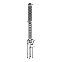
CB assy. -- Control Section
CB positional indicator status
Discon
nector position
indica
tor
status
Low voltage
cabine
t
6
7
8
2
F
P
o
l
e
s
h
e
a
t
h
1
0

Related product manuals