EasyManua.ls Logo

Alstom FKG1X - Page 47

Alstom FKG1X
274 pages
To Next Page IconTo Next Page
To Previous Page IconTo Previous Page
Loading...
Description and operation
Electrical components complementary
to the circuit breaker
G12
-
-0
53EN02
2/6
02--2011
© ALSTOM 2010. All rights reserved. Informat
ion contained in
this document is indicative only. No
representati
on or
warrant
y is
given or should
be
relied on that it is complete or correct or will apply to any particular project. This will depend on the technical and commercial circumstances. It is
provided without liabili
ty and
is subject to
change without notice. Reproduction, use or disclosure to
third parties, without express writt
en authority, is
strictly prohibited.
GRID
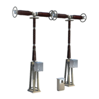
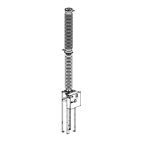
Busbar disconnector switch
Illustration
3
42
36
37
5
35
38
4
Table of
the
compone
nts
The following table lists the principle components of the busbar disconnec-
tor switch :
M
a
r
k
C
o
m
p
o
n
e
n
t
F
u
n
c
t
i
o
n
3
C
B
-
-
mo
vi
ng
pa
rt
4
D
i
s
c
o
n
n
e
c
t
o
r
F
i
x
e
d
p
a
r
t
-
-
5
O
p
e
r
a
t
i
n
g
s
h
a
f
t
T
r
a
n
s
m
i
t
s
m
o
v
e
m
e
n
t
.
3
5
O
p
e
r
a
t
i
n
g
l
e
v
e
r
A
c
t
u
a
t
e
d
b
y
t
h
e
r
o
d
l
i
n
k
a
g
e
(
4
2
)
i
t
transmits movement to the shaft (5).
36
Di
sc
on
ne
ct
or
mo
vi
ng
pa
rt
casing
-
-
3
7
I
n
s
u
l
a
t
o
r
m
o
u
n
t
i
n
g
-
-
3
8
M
o
b
i
l
e
c
o
n
t
a
c
t
A
l
l
o
w
s
c
u
r
r
e
n
t
t
o
p
a
s
s
b
e
t
w
e
e
n
t
h
e
fix
ed
pa
rt
(4
)
an
d
th
e
mo
vi
ng
pa
rt
(3
6)
of the disconnector switch casing.

Related product manuals