must be ventilated to prevent an excessive temperalure rise.
Because transistors are heat sensitive, the 15948 should not
be placed adjacent to heat
-
generating equipment or in areas
where
ambient temperature exceeds 55'~ (131'~).
If the 15948
is
installed in an equipment rack or cabinet
with other heat
-
producing equipment installed above andlor
below (two or more 15948's or one 15948 with real time
analyzer, oscilloscope, etc.), space must be provided be
-
tween the units or the 15948 may become too warm. The
1-314" perforated panel (ALTEC Part No. 10399)
is
recom
-
mended for this purpose. When several amplifiers or other
heat
-
producing units are installed in a single rack or
cabinet, acceptable air temperature may be in
do~~bt. To
determine temperature conditions, operate the system until
temperature stabilizes, then measure air temperature with a
bulb
-
type thermometer held at the bottom of the upper
-
most amplifier. Do not let the thermometer bulb touch
metal because the metal probably will be hotter
Than the
ambient air. If air temperature exceeds
55'~ (or if it
is
a
hot day), the equipment should be spaced farther apart or a
blower should be installed to ventilate the cabinet.
CAUTION
Do not block the
cvver ventilation holes
when placing other equipment on the
42526 Shelf Mount Cover accessory.
When shelf
-
mounting the 15948. allow at
least
1-314" between the unit and any
wall behind it to assure air circulation
past the output transistors.
ELECTRICAL
120 Volt,
50160
Hz
Power Connections
Equipment supplied for domestic use is provided with the
power transformer primary strapped for 120 volts (terminals
BATTERY POWER
TERMINAL BOARD
(TB4)
1
to 2 and
3
to
4
on TB3). The power input nameplate,
adjacent to the power cord on the chassis,
is
mounted to
show the appropriate side specifying the connections (see
Figure 6). Verify that line voltage
is
in accordance with the
voltage rating before connecting the
15948 to line power.
240 Volt,
50160
Hz
Power Connections
Export equipment
is
provided with the power transformer
primary strapped for 240 volts (terminals 2 to 3 on
TB3).
The power input nameplate, adjacent to the power cord on
the chassis,
is
mounted to show the appropriate side specify
-
ing the connections.
For a 15948 previously wired for
120V ac primary power,
use the following procedure to change wiring for 240V ac,
50160
Hz
operation:
Step
1.
Remove four screws securing front panel, open
and lower panel.
Step 2.
Locate terminal board TB3 above power trans.
former
TI (see Figure 5).
Step 3.
Remove strap
"
A
"
connecting terminals 1 and
2 and remove strap
"8" connecting terminals 3
and
4;
solder strap
"
C
"
to terminals
2
and
3
(see Figure
7).
Step 4.
Remove voltage
-
rating plate
(see
Figure 6) from
chassis, reverse and reinstall to show 240V ac
rating.
Step
5.
Close front panel and secure with four screws
previously removed.
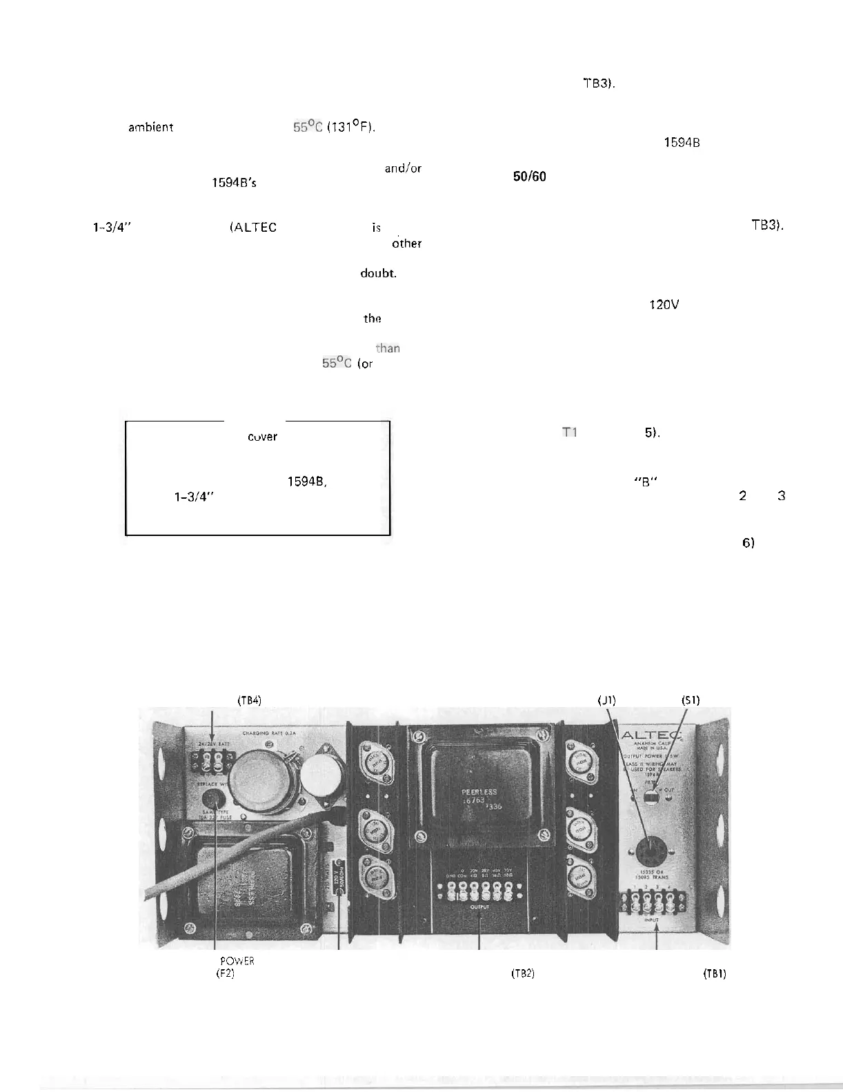
TRANSFORMER
ACCESSORY FILTER
RECEPTACLE SWITCH
(J1)
(51)
BATTERY
POWER
VOLTAGE OUTPUT INPUT
FUSE
(F2)
RATING TERMINAL BOARD
(TB2)
TERMINAL BOARD (TBI)
PLATE
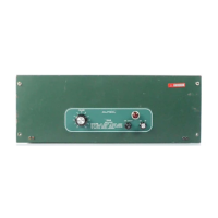
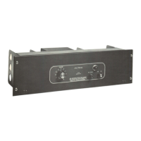
Figure 6. Rear View of 15948 Power Amplifier
 Loading...