Figure
7.
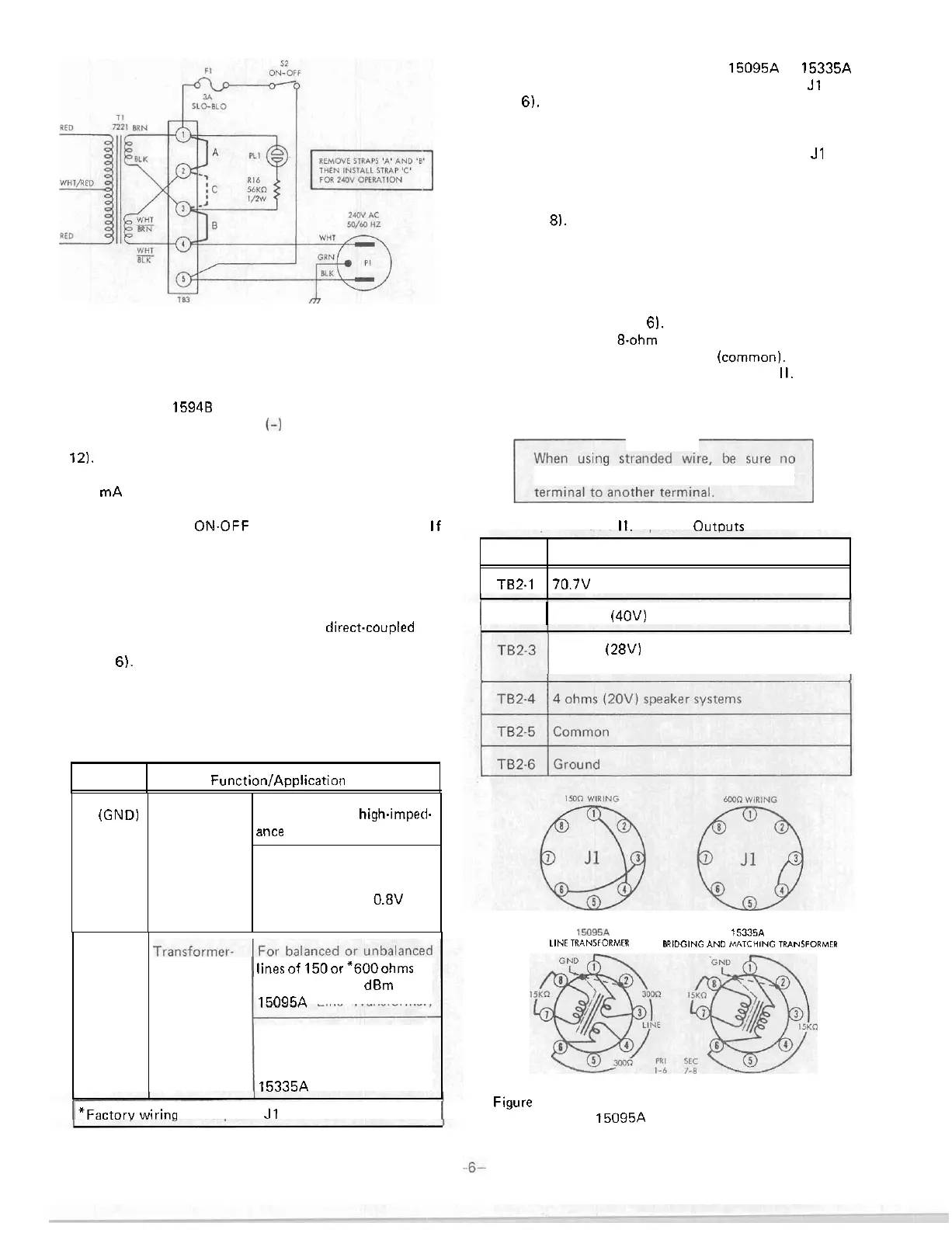
Converting to 240V ac, 50160
Hz
Operation
Battery Connections
If desired, the
15948 may be connected to an external
24/28 volt battery with minus
(-1
as
ground. Terminals for
the dc power connections are on TB4 (see Figures 6 and
12). If ac power fails, transfer to dc power
is
instantaneous,
automatic and silent. A built
-
in charging circuit supplies
a
100 mA trickle current to maintain battery charge during
ac operation. The battery power supply
is
not operated by
the primary power
ON.OFF switch on the front panel, If
switching of battery power
is
desired, an external relay or
switch should be provided by the user.
lnput Connections
lnput connections may be either
direct.coupled or
transformer
-
isolated
at
the INPUT terminal board (see
Figure
6). Direct coupling
is
accomplished by connecting
the input leads (shielded conductor recommended) to
terminals 1 and
2.
Terminal 2
is
ground. Table
I
lists the
terminals and applications of the INPUT terminal board.
Table
I.
Terminals and Applications of
INPUT Terminal
Terminals
1.2
(GND)
For transformer
-
isolated input,
a
plug
-
in 15095A or 15335A
Line Transformer must be plugged into receptacle J1 (see
Figure
6). The input leads
are
connected to terminals
3
and
4 of the INPUT terminal board.
Function/Application
3.4
When shipped from the factory, pins 3 and 4 of
J1
are
strapped together to provide
a
600
-
ohm input. A 150
-
ohm
input may be obtained by removing the strap from pins
3
and 4 and then strapping pins 1 and
4
and pins 3 and 6
(see Figure
8).
I
Direct
-
Coupled
Isolated
linesof 150or "600ohms up
to level of +15
dBm (with
15095A Line Transformer)
For low
-
impedance line
-
bridging input or 15K ohrn
line
-
matching input (with
15335A Line Transformer)
Output Connections
For unbalanced
high-imped-
ance sources
For bridging unbalanced
low
-
impedance lines having
signal voltages of
0.8V rms
or higher
Output transformer taps provide connections for 4
-
ohm,
8
-
ohm and 16
-
ohm speakers, plus
a
70.7
-
volt speaker distri
-
bution system (see Figure 6). For 25
-
volt speaker distribu
-
tion systems, use the 8.ohrn tap. Connect to the terminal
of desired impedance and terminal 5
(common). Terminal
functions and designations are listed in Table
II. If stray
electrostatic radiation causes interference, strap terminal 5
(common) to terminal 6 (ground).
CAUTION
frayed wire strands short circuit one
Table
II.
Soeaker Outouts
I
TB2
-
2
1
16 ohms (40V) speaker systems
I
Terminal
8 ohms
(28V) speaker systems. May be used
for 25V speaker distribution systems.
Function
1M95A
15335A
LINE
TWNIIORMER
BRIDGING AND
MTCHING
TRANSFORMER
I
'Factorv wirina
at
receotacle
J1
is
for 600 ohms
I
TB2-1
Figure
8.
Socket Wiring for Transformer
-
Isolated Input
Using
15095A Line Transformer
70.7V (50 ohms) speaker distribution systems
 Loading...