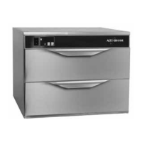
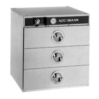
WARMING CABINET CHARACTERISTICS
The cabinet is equipped with a special, low-heat-density,
heating cable. Through the HALO HEAT concept, the heat-
ing cable is mounted against the walls of the warming com-
partment to provide an evenly applied heat source controlled
by a thermostat. The design and operational characteristics
of the cabinet eliminates the need for a moisture pan or a heat
circulating fan. Through even heat application, the quality of
a food product is maintained up to as much as
several hours.
THERMOSTAT AND
PILOT LIGHT SEQUENCE
Whenever the thermostat is turned up, the pilot light will
indicate the power ON/OFF condition of the heating cable,
and consequently, the cycling of the cabinet as it maintains
the dialed cavity temperature. If the pilot light does not indi-
cate after normal start-up, the main power source, thermo-
stat, and/or the pilot light must be checked. If a warming
compartment does not hold the temperature as dialed, the
calibration of the thermostat must be checked. (See the para-
graph on thermostat calibration.) If a warming compartment
fails to heat or heats continuously with the thermostat OFF,
the thermostat must be initially checked for proper operation.
If all is in order, a continuity and resistance check of the heat-
ing cable should be made. (See the circuit
diagram.)
THERMOSTAT CALIBRATION
The thermostat is precision calibrated at the factory.
Normally, no adjustment or recalibration is necessary unless
the thermostat has been mishandled in transit, changed or
abused while in service. A thermostat with a sensing bulb
operates on hydraulic pressure. Consequently, any bending
of the bulb results in a change in its volume and displaces the
accuracy of the thermostat calibration.
A thermostat should be checked or recalibrated by plac-
ing a quality temperature indicator at the center of an empty
warming cavity. DO NOT CALIBRATE WITH FOOD PROD-
UCT IN THE WARMING CABINET. The temperature must
be allowed to stabilize at one particular setting for at least
one hour. Following this stabilization period, the center of
the thermal swing of the cavity temperature should approxi-
mately coincide with the thermostat setting.
The calibration screw of the thermostat is located in the
dial shaft, and should be adjusted with great care and cau-
tion. With the shaft held stationary, a minute clockwise
motion of the calibration screw APPRECIABLY lowers the
thermostat setting while a reverse, counter-clockwise motion
results in the opposite condition. After achieving the desired
cycling of the thermostat, the calibration screw must be
sealed in place with a few drops of sealant.
[RED NAIL POLISH OR EQUIVALENT IS ACCEPTABLE.]
QUANTITY ALTO-SHAAM
10/13/98 PART DESCRIPTION PER UNIT PART NO.
1. TOP 1 11369
2. TOP MOUNTING SCREWS 4 SC-2459
3. POWER CORD (125V) 1 CD-3232
CORD SET: 230V INTL (TYPE HO7 RN-F) 1 CD-3984
CORD SET: 208-240V) 1 CD-3858
4. POWER CORD STRAIN RELIEF BUSHING
(125V) 1 BU-3011
INLET (208-240V) 1 IT-3857
INLET (230V) 1 IT-33173
5. CASING BACK 1 11380
6. CASING BACK MOUNTING SCREWS 2 SC-2459
7. DRAWER ASSB. 1 5303
DRAWER ASSB. W/VENTS (
OPTION - NOT SHOWN) 1 15418
EACH ASSEMBLY INCLUDES:
— DRAWER PULL 1 PL-2005
— PAN SPACERS 2 11398
— PAN SPACER MOUNTING SCREWS 4 SC-2459
— DRAWER BEARINGS 4 BG-2410
8. DECOR PANEL (125V) 500-1D 1 5744
DECOR PANEL (208-240V) 500-1D 1 5743
9. WATTAGE SWITCH (125V only) 1 SW-3409
10. THERMOSTAT 1 TT-3057
11. HEAT INDICATOR LIGHT (125V) 1 LI-3027
HEAT INDICATOR LIGHT (208-240V,230V) 1 LI-3951
12. TEMPERATURE GAUGE 1 GU-33384
13. CASING ASSEMBLY 1 4336
14. INSULATION: 22" x 43" (559mm x 1092mm) 1 IN-2381
15. CABLE CONNECTION HARDWARE
16. FAN (125V) 1 FA-3485
FAN (208-240V,230V) 1 FA-3342
FAN BLADE 1 FA-3343
17. HEATING CABLE: Length 104' (31699mm) 1 CB-3044
18. CABINET DRAWER RAIL ASSEMBLY
(
NOT SHOWN) 1 5331
19. CABINET DRAWER RAIL ASSEMBLY
MOUNTING STUD (
NOT SHOWN) 4 ST-2547
20. CABINET DRAWER RAIL ASSEMBLY
MOUNTING NUT (
NOT SHOWN) 4 NU-2437
21. CABINET DRAWER BEARINGS (
NOT SHOWN) 2 BG-2410
22. DRAWER PAN (
NOT SHOWN) 1 PN-2123
O PERATION AND C ARE M ANUAL #818 • 3
DISCONNECT UNIT FROM POWER
SOURCE BEFORE CLEANING
OR SERVICING
SERVICE VIEW PARTS LISTS
MODEL 500-1D
 Loading...