Do you have a question about the Alto L-16 and is the answer not in the manual?
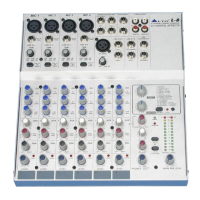
Details the features of the input channel strips, including faders, EQ, and connectivity.
Describes the master section capabilities, including DSP effects, graphic EQ, and outputs.
Details specifications for mono and stereo input channels, including frequency response and gain.
Lists input/output impedance values and equalization band specifications.
Details DSP converter specs, effect types, and main mix/AUX send levels.
Specifies AC input voltage ranges for different regions (USA, Europe, UK/Australia).
Details power usage, fuse ratings for different voltage ranges, and main connection type.
Provides a high-level overview of the audio signal flow through the device.
Details circuits for control room output, aux sends, and main insert.
Details stereo aux return, balanced main output, and subwoofer insert circuits.
Details headphone output and tape interface circuitry.
Shows the block layout for channels 1 through 4.
Details EQ, pan, level, mute, and aux send circuitry for channel 1.
Details EQ, pan, level, mute, and aux send circuitry for channel 2.
Details EQ, pan, level, mute, and aux send circuitry for channel 3.
Details EQ, pan, level, mute, and aux send circuitry for channel 4.
Details stereo input channel schematics for channels 5 through 12.
Covers other I/O interfaces and aux return paths.
Shows control room meter and DSP block schematics.
Details EQ, pan, level, mute, and aux send circuits for stereo channels.
Details EQ, pan, level, mute, and aux send circuits for stereo channels 9-12.
Details main output and subwoofer signal paths, including 2TK to Mix.
Illustrates the implementation of the 9-band graphic equalizer.
Details the circuits for all auxiliary return paths (1-4).
Shows connections to main mix and monitor outputs, including DFX.
Details the circuits for all auxiliary send paths (1-4).
Shows the digital effects send path.
Details signal sources, routing, and VU meter circuitry for control room.
Details EFX processing, interface, and footswitch circuits.
Details AC input, transformer, and phantom power circuitry.
Shows regulated voltage rails and power outputs.
Details audio converter and memory IC schematics.
Shows logic gates, power regulation, and interface components.
Shows how different PCBs and modules connect within the system.
Details connections to power supply, DSP, and lamp.
Lists test equipment and initial setup steps.
Outlines the functional testing process for various inputs and outputs.
Describes testing the frequency response of line inputs.
Presents frequency response curves for EQ adjustments.
Provides final test remarks, DSP testing, and sampling test steps.
| Channels | 16 |
|---|---|
| Microphone Inputs | 8 |
| Line Inputs | 8 |
| Aux Sends | 4 |
| Phantom Power | Yes |
| Faders | 16 |
| Other Inputs | 2 |
| Main Outputs | 2 |
| Other Outputs | 2 |
| USB Interface | Yes |
| Type | Analog Mixer |
| EQ Bands | 3-band |
| Effects | Built-in |