Instruments required:
1) Sinusoidal signal generator, 5) Resistive load 4 Ω 800W,
2) Dual trace scope, with probe, 6) Resistive load 8 Ω 300W
3) Digital multimeter, 7) Pink noise from the GM “AUDIO CD”.
4) Variac 0-250 Vac,
P.S: Isolate the oscilloscope from earth and adjust the two traces on center of screen in GND
position.
Par. 1: visual check
- Make a visual check if the amplifier is perfectly done and especially verify:
a) the right value of fuses 6.3A 250V *4PCS
b) the right earth main connection on rear surface of front panel.
c) the insulation between the heat-sink and the case of TR1-15, IC1, 2, 3, 4 -then,
- Set the VOLUME control full clockwise.
Par. 2: connections
- Switch off the amplifier module,
- Set the ENCODER pot. on preset “NORMAL”.
- Connect the mains of amplifier module to VARIAC and set it at zero AC voltage.
- Connect the signal generator to Line Input (XLR socket) and set it at 500Hz, 0dB .
- Connect the scope CH1 probe to amplifier low output and CH2 probe to amplifier high output-
Par. 3: Initial test
- Increase slowly the VARIAC voltage up to the nominal value (230Vac).
- Check the transformer sec. voltages with multimeter, (without signal on input):
S1-S2: 90V ±1.5Vac
S4-S5: 47V ±1.5Vac
- Check the +/-15Vdc supply on relative voltage regulator outputs (IC3 & IC4 devices).
- Switch ON the signal generator and verify that the output signals must be symmetrical referring
to GND, without detectable distortion and oscillation.
- Check that the low amplifier power output signal is 28+2V
PEAK
(19.5V
RMS
)
.
- -Check of SIGNAL led function, moving the volume potentiometer of amplifier;
when the output signal is <0.5V
peak
the led must be OFF,
when the output signal is > 0.5V
peak
, the led must be GREEN lighted.
-Then, rotate the volume potentiometer knob full clockwise
Par. 4: BOOSTER check of LOW Amplifier
- Connect alternatively the CH2 probe tip of scope on D2 cathode and D3 anode and
verify the following conditions:
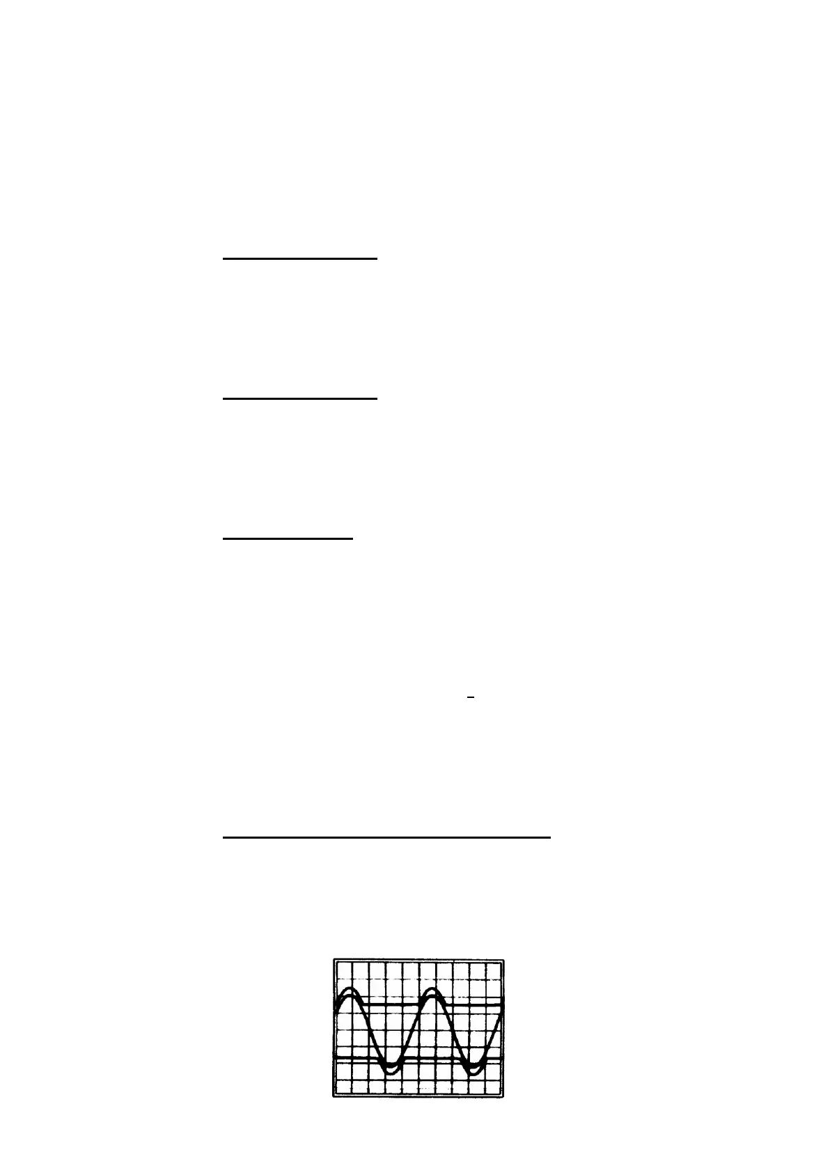
when the output signal is < 18Vrms the ±VCC1 voltage must remain linear at 28V,
when the output signal is > 18Vrms the ±VCC1 voltage must follow the output signal wave with
4Vdc offset, as shown in the following picture
 Loading...