02 ULADA Application Guide - 3 -
3. Non-synchronizable NAC Appliances:
When using NAC appliances not designed to support synchronization feature, it is recommended to use
separate output circuits for audible notification appliances (horns) and visual notification appliances (strobes).
Set DIP switches for the visual notification appliances to follow Input 1 [IN1] and for audible notification appli-
ances to follow Input 2 [IN2]. This will allow, when using two (2) outputs from the FACP, to support silencing
of audible notification appliances. When using only one (1) FACP output, set all DIP switches to follow Input 1
[IN1]. The units outputs can each be set for the desired NAC drive signal, such as Code 3 or march time sequence
(Output Programming Selection Table, pg. 6). Non-synchronizable Audible Appliances will follow the sequence,
when feature is selected.
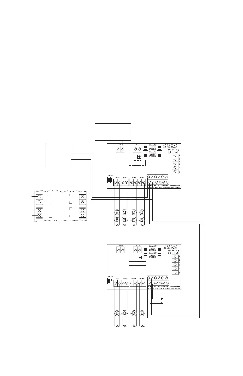
4. Using Multiple NAC Power Extenders from an FACP:
AL602/AL802/1002ULADA(J)/R1002ULADA units are designed to follow (replicate) the coded sequence,
generated by a manufacturer’s sync module. One (1) or more units can be triggered. Connect the output of the
FACP module to Input 1 and Input 2 Terminate the input circuit with the EOL or FACP, connecting it to terminals
marked [RET +] and [RET –], or continue the input circuit, connecting to terminals marked [RET +] and [RET –]
to [INP +] and [INP –] of the next unit, when multiple units need to be triggered.
In case FACP does not have any synchronization capabilities and the sync mode is not used,
the notification appliance synchronization will not be provided.
FACP with Sync Output
Control
Circuit
Control Circuit
No Notification Appliances Allowed
Sync Module
NAC Power Extender:
DIP switches set to Input to Output follower mode.
POWER
IN +
POWER
IN ---
ZONE 1
POWER
IN +
POWER
IN ---
HORN
CONTROL
POWER
OUT +
POWER
OUT ---
ZONE 1
POWER
OUT +
POWER
OUT ---
ZONE 2
+ NAC 1 --- + NAC 2 ---
2.2K
EOL
2.2K
EOL
2.2K
EOL
2.2K
EOL
FACP
(Fire Alarm
Control Panel
with sync
capabilities)
Or
Memory
Reset
To FACP EOL or
next NAC power extender
For Class A configuration
return to FACP
Memory
Reset
NAC Power Extender:
DIP switches set to Input to Output follower mode.
ON
1
ON
1
ON
1
ON
1
Compatible Special
Application Devices.
See Compatibility List
Fig. 4a
CAUTION: Do not connect any notification appliances on the control circuit interconnecting
FACP outputs (sync module outputs) and inputs of NAC Power Extenders. Applications that
do not employ synchronization module or FACP with synchronization protocol will not provide
NAC sycnchronization between NAC Power Extenders.
 Loading...