EasyManua.ls Logo

Altronix AL802ULADAJ User Manual

Altronix AL802ULADAJ
16 pages
To Next Page IconTo Next Page
Page #1 background imageLoading...
Page #1 background image
Altronix Corp.
140 58th St. Brooklyn, NY
AL802ULADAJ
NAC Power Extender
Installation Guide
(see Application Guide for additional information)
Rev. 111819
More than just power.
TM
Installing Company: _______________ Service Rep. Name: __________________________________
Address: _____________________________________________ Phone #: __________________

Other manuals for Altronix AL802ULADAJ

Question and Answer IconNeed help?

Do you have a question about the Altronix AL802ULADAJ and is the answer not in the manual?

Altronix AL802ULADAJ Specifications

General IconGeneral
BrandAltronix
ModelAL802ULADAJ
CategoryExtender
LanguageEnglish

Summary

Overview

Battery Backup

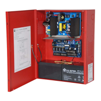
Covers charging voltage, battery type, and automatic switchover.

Power Supply Specifications

Installation Instructions

Mounting and Grounding

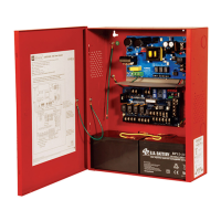
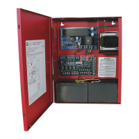
Instructions for mounting the unit, securing it, and grounding.

AC Input Connection

Connects the 120VAC, 60Hz circuit to the unit's line and neutral terminals.

Battery Connection

Connects the sealed lead acid or gel type batteries to the unit.

FACP Output and Appliance Connection

Connects FACP outputs to logic board inputs and appliances to logic board outputs.

Output Programming Selection Table

Sync Mode Selection Table

AL800LGK9E Logic Board Terminal Identification

IN1, IN2 Terminals

Terminals for connecting 24VDC FACP notification appliance circuit outputs.

+OUT1 to +OUT4 Terminals

Regulated power-limited NAC output terminals, each supplying 2.5A.

AL800ADA Power Supply Board Terminal Identification

L, G, N Terminals

Terminals for connecting 120VAC input: L to hot, N to neutral.

DC+ Terminal

24VDC @ 8A alarm non power-limited output.

+ BAT - Terminals

Stand-by battery input terminals.

LED Diagnostics

AL800LGK9E Logic Board LED Status

Details LED status for outputs, inputs, and fault conditions.

Battery Calculation Worksheet

Device Current Draw

Stand-by and alarm current draw for AL802ULADAJ and auxiliary devices.

Notification Appliances Current

Total current for notification appliances, not exceeding 8A.

Total Alarm Current Calculation

Calculates total alarm current by summing device and appliance currents.

Stand-by and Alarm Hour Calculation

Calculates required ampere-hours for stand-by and alarm periods.

Total Ampere-Hours Required

Determines total ampere-hours needed, including a 30% safety margin.

Hookup Diagram

AC Input Wiring

Diagram showing unswitched 120VAC power connection.

Battery and DC Output Wiring

Diagram showing supervised non-power-limited battery and non-power-limited DC+ connections.

Logic Board Terminal Connections

Diagram showing connections for inputs, outputs, fault, AUX, and DC+.

Maintenance

Annual Testing

Unit should be tested at least once a year for proper operation.

Output Voltage Test

Check DC output voltage under normal load conditions (26.2-26.4VDC).

Battery Test

Check battery charge and connection integrity at terminals.

Appendix A: Compatible UL/cUL Listed Devices for Synchronization

Appendix A (cont'd): Compatible UL/cUL Listed Devices for Synchronization

Related product manuals